
Operating instructions

40
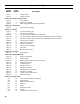
Appendix A - Figures
Figure
Number
Page
Number
Description
Figure 1 3 Elevation Views
Figure 2 2 Tapping Locations
Section III - Steam Piping and Trim
Figure 3 7 Trim Installation
Figure 4 7 Steam Piping, IN3PVNI
Figure 5 8 Steam Piping, IN4PVNI, IN5PVNI and IN6PVNI
Section IV - Gas Piping
Figure 6 9 Recommended Gas Piping
Section V - Venting
Figure A 10 U.S. Boiler Company Vent
Figure 7 11 Vent Connector Installation
Figure 8A 12 U.S. Boiler Company Gasketed Vent Joint Detail
Figure 8B 12 U.S. Boiler Company Gasket-Less Male and Gasketed Female Vent Joint Detail
Figure 8C 13 U.S. Boiler Company Gasket-Less Female and Gasketed Male Vent Joint Detail
Figure 9 13 Horizontal Vent Installation
Figure 10 14 Horizontal Vent Terminal
Figure 11 14 Vertical Vent Installation
Figure 12 15 Vertical Vent Tee Installation
Figure 13 15 Attic Offset
Figure 14 15 Vertical Vent Termination
Section VI - Electrical
Figure 15 16 Wiring Diagram
Section VII - System Start-Up
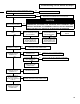
Figure 16 17 Sequence of Operation
Figure 17A 17 Location of LED
Figure 17B 19 Measuring Pilot Flame Current w/Micro-ammeter
Figure 18 20 Troubleshooting Guide
Figure 19 21 Pilot Burner Flame
Figure 20 21 Main Burner Flame
Figure 21 22 Operating Instructions
Figure 22 26 Cleaning Boiler Flue Passages
Figure 23 26 Main Burner Installation
Figure 24 27 Inlet Fan Vacuum Measurement
Figure 25 27 L404F Pressuretrol
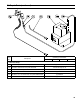
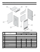
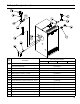
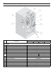
Section IX - Repair Parts
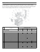
N/A 32 Section and Canopy/Blower Assemblies
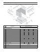
N/A 33 Base Assembly
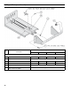
N/A 34 Manifold and Main Burners
N/A 35 Gas Train
N/A 36 Jacket
N/A 37 Miscellaneous Parts
N/A 38 Controls
N/A 39 Gasketed Vent Accessory Carton