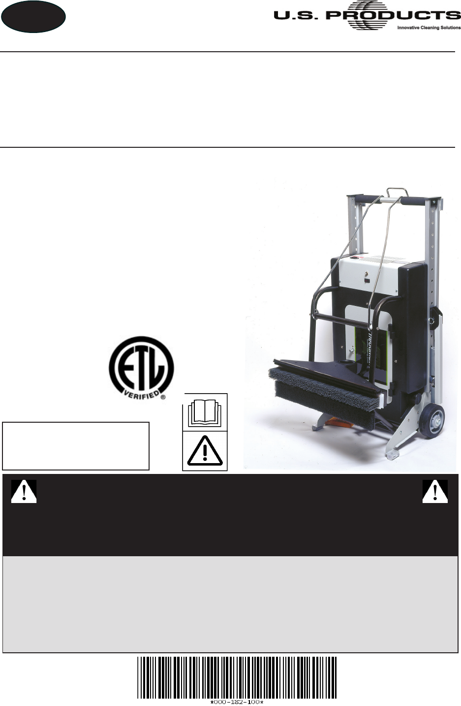
EN TREADMASTER™ ESCALATOR CLEANER INFORMATION AND OPERATING INSTRUCTIONS Models 100-100-001 Models 100-100-221 100-100-002 100-100-222 100-100-003 100-100-223 100-100-004 100-100-005 SAVE THESE INSTRUCTIONS IMPORTANT SAFETY INSTRUCTIONS When using an electrical appliance, basic precautions should always be followed, including the following: READ ALL INSTRUCTIONS BEFORE USING THE TREADMASTER U.S. Products 11015 47th Avenue West, Mukilteo, Washington 98275 MAN-44183 Rev.
EN EN = ENGLISH (120 V/230 V) FR = CANADIAN FRENCH (120 V)
EN Table of Contents GENERAL INFORMATION.............................................................................................. 1 Approvals/Certifications.............................................................................................. 3 Contact Information..................................................................................................... 4 Warnings, Cautions and Notices.................................................................................
EN ASSEMBLIES AND PARTS LISTS............................................................................... 33 Parts and Support..................................................................................................... 33 Configurations........................................................................................................... 34 Frame Housing Assembly (120V) Parts List............................................................. 38 24” Nylon Grit Head Assembly....................
EN List of Figures Figure 1. Accurate Measurements Needed Before Ordering Brush and Head Assembly............................................................11 Figure 2. Position Assemblies Together, on Flat Surface.............................................. 13 Figure 3. Fluted Knobs Removed from Head Assembly; Nozzle Facing Outward........ 13 Figure 4. Position Pad Holder Lift Arm on Head Assembly........................................... 14 Figure 5.
EN Figure 30. 37” Nylon Grit Head Assembly...................................................................... 47 Figure 31. Left Rail and Heel Plate Assembly................................................................ 49 Figure 32. Right Rail and Heel Plate Assembly.............................................................. 51 Figure 33. Left Extension Arm Assembly........................................................................ 53 Figure 34. Right Extension Arm Assembly....................
EN GENERAL INFORMATION The TreadMaster is a specialized machine designed to clean escalators and moving sidewalks (horizontal “people movers”) in commercial establishments such as airports, hotels, shopping malls, schools, hospitals, factories, shops and offices. Housing Assembly Head Assembly It is simple to set up and automatic in its operation. The TreadMaster’s weighted head assembly fits down into the tread of the escalator to loosen soil and debris.
EN This document contains operation instructions as well as information required for proper maintenance of the TreadMaster. It is the purpose of this document to help you properly understand, maintain and service your TreadMaster. Follow the directions carefully and you will be rewarded with years of profitable, trouble-free operation. It is imperative that no section of this document be overlooked when operating and maintaining the TreadMaster.
EN APPROVALS/CERTIFICATIONS CSA Approved Your machine has been designed and tested to comply with the Canadian standard for this class of equipment. It has been tested under the following standard: CSA C22.2#243 Issue:2001/12/07 Ed. 3 Rev:2001/06/15 Vacuum Cleaners, Blower Cleaners, and Household Floor Finishing Machines; General Instruction No 1; UL 1017 (R2006) If it is necessary to provide verification, your machine is labeled with an ETL mark.
EN CONTACT INFORMATION If you have any questions regarding the operation, maintenance or repair of this machine, refer to the following information and contact the appropriate U.S. Products department. Hours Telephone Numbers Monday-Friday (425) 322-0133 Support 7:00 a.m. to 5:00 p.m. (800) 257-7982 Parts Pacific Time FAX (425) 322-0136 E-mail Addresses Tech Support: techsupport@usproducts.com Parts Support: csorders@usproducts.
EN WARNINGS, CAUTIONS AND NOTICES U.S. Products uses this WARNING symbol throughout this document to warn of possible injury or death. This CAUTION symbol is used to warn of possible equipment damage. This NOTICE symbol indicates that federal or state regulatory laws may apply, and also emphasizes supplemental information.
EN Warnings and Cautions specific to the TreadMaster include the following. To reduce the risk of fire, electric shock, or injury: Turn off all controls before unplugging the TreadMaster. Failure to do so can cause bodily injury. Unplug the TreadMaster from outlet when it is not in use and before servicing. Failure to do so can cause bodily injury. Do not unplug the TreadMaster by pulling on its cord. To unplug, grasp the plug, not the cord.
EN Do not use with damaged cord or plug. If appliance is not working as it should, has been dropped, damaged, left outdoors, or dropped into water, return it to a service center. Failure to follow this warning can result in the possibility of electric shock, serious bodily injury and/or death. Do not pull or carry by cord, use cord as a handle, close a door on cord, or pull cord around sharp edges or corners. Do not run appliance over cord. Keep cord away from heated surfaces.
EN Before setting up the machine, turn off the escalator or moving sidewalk. Failure to do so can cause bodily injury. This appliance must be grounded. Connect to a properly grounded outlet only. See Grounding Instructions on page 17 of this document. Failure to properly ground the equipment can result in the possibility of electric shock and serious bodily injury or death. If the plug on the power cord is damaged, dispose of the cord.
EN MACHINE SPECIFICATIONS Housing Assembly Dimensions 21.5” W x 31.
EN TREADMASTER OPTIONS AND ACCESSORIES Part Number Description 190-100-014 Head Assembly, 22” w/ Nylon Grit Brush 190-100-011 190-100-012 Head Assembly, 24” w/ Nylon Grit Brush Head Assembly, 32” w/ Nylon Grit Brush 190-100-015 190-100-013 190-100-002 190-100-201 101-100-028 101-100-029 101-100-030 105-100-018 105-100-019 105-100-020 000-016-062 000-016-063 000-016-064 000-016-060 101-100-031 101-100-032 101-100-033 000-078-201 000-078-203 000-078-205 000-049-115 000-031-105 Head Assembly, 37” w/ Nyl
EN MEASURING INFORMATION Before ordering an additional or replacement head assembly, be aware that specific measurements are needed to effectively and efficiently process your order. To properly measure the escalator or moving sidewalk, refer to Figure 1 and follow these guidelines: 1. With a measuring device, measure the horizontal distance from side wall to side wall, on the bottom step (see solid arrows in Figure 1).
EN TreadMaster Information and Operating Instructions - 12
EN INSPECTION, INSTALLATION AND TRANSPORTING INSPECTING ASSEMBLIES After receiving your TreadMaster, carefully unpack the boxes and inspect the housing assembly, brush and head assembly for shipping damage. No matter which TreadMaster configuration you order (see Table 1 and Table 2 on 34), you can receive up to three major assemblies in your shipment unless you specify otherwise: 1. 2. 3.
EN 3. Position the housing assembly’s lift arm onto the head assembly, aligning the mounting holes on the lift arm with the fasteners on the head assembly (see Figure 4). Lift Arm Lift Arm Latching Bail Handle Figure 4. Position Pad Holder Lift Arm on Head Assembly 4. Secure the head assembly to the lift arm by re-installing the two fluted knobs (see Figure 5). Figure 5. Secure Head Assembly with Fluted Knobs; Attach Hose to Nozzle 5. Figure 6.
EN INSERTING A DIFFERENT BRUSH INTO HEAD ASSEMBLY If you want to replace a brush — for example, in the case of removing the nylon grit brush and replacing it with the Soft brush for painted escalators — follow these steps: 1. 2. Turn off the TreadMaster. Loosen the thumb screw on the head assembly (see Figure 7). Thumb Screw Slide Brush Out of Head Assembly Figure 7. Loosen Thumb Screw and Slide Brush Out of Head Assembly 3. 4. 5. 6. Slide the brush out of the head assembly. Insert the new brush.
EN TRANSPORTING/STORING THE TREADMASTER To move or store the TreadMaster: 1. Turn off the TreadMaster. 2. Unplug the cord from the power source and the TreadMaster. 3. Store the cord and the escalator cleaning sign in the storage compartment. 4. Attach the latching bail handle to the end of the housing assembly’s handle as shown in Figure 8. 5. Position the TreadMaster in the upright position. Latching Bail Handle Figure 8.
EN GROUNDING INSTRUCTIONS During operation, the TreadMaster must be electrically grounded. If it should malfunction or breakdown, grounding provides a path of least resistance for electric current to reduce the risk of electric shock. This appliance is equipped with a cord which has an equipment-grounding conductor and grounding plug. The plug must be inserted into an appropriate outlet that is properly installed and grounded in accordance with all local codes and ordinances.
EN TreadMaster Information and Operating Instructions - 18
EN OPERATING INSTRUCTIONS PREPARATION 1. Ensure that the escalator is not moving. 2. Wheel the TreadMaster to the escalator or moving sidewalk in the TreadMaster’s upright position (see Figure 9). Figure 10. TreadMaster Shown in Preferred Placement, at Bottom of Escalator Figure 9. TreadMaster Shown in Upright Position Figure 11. TreadMaster Shown in Flat Position Always place the TreadMaster where the steps are moving away from the unit.
EN “Escalator Cleaning in Progress” Sign Power Switch Handle Storage Compartment Restraining Arm Leveling Adjustment Knob Cleaning Head Level Built-In Vacuum System Quiet Ride Wheels Vacuum Hose Replaceable Polishing Pad and Brushes Pad Holder Lift Arm Adjustable Cleaning Head Figure 12. Components of TreadMaster Do not operate this machine without the restraining arms in place as it could damage the TreadMaster and/or the escalator/moving sidewalk.
EN 6. 7. 8. 9. 10. Slide the restraining arms in their channel to position the cleaning head over the tread. Notice that the pin in the end of the arm will fit into one of the holes in the channel, locking the arm into place. Extend the restraining arms to their full locked position (see Figure 12 and Figure 13). Slide the TreadMaster into the treadwell, making sure the restraining arms are firmly seated against the balustrades (see Figure 13).
EN OPERATION 1. 2. 3. To seat the cleaning brush in the grooves, set the polishing pad holder lift arm in the "up" position (see Figure 16). Attach the warning sign to the crossbar handle (see Figure 13). Plug in the power cord at the machine receptacle first; then, plug the cord into the nearest rated outlet. Polishing Pad Holder Lift Arm Figure 16. Set Lift Arm in Up Position 4. 5. 6. Prior to starting the escalator/moving sidewalk, review Steps 2 – 11 on pages 19 – 21.
EN POLISHING Pull the pad holder lift arm back toward the machine and down (see Figure 16). This lowers the polishing pad to the tread surface and simultaneously lifts the brush bristles from the grooves. TOUCH-UP CLEANING HINTS Perform these simple steps to prolong the service life of your equipment and reduce replacement costs: 1. Disconnect the hose from the vacuum head and attach the crevice tool. 2.
EN TreadMaster Information and Operating Instructions - 24
EN DAILY MAINTENANCE Before performing any maintenance on the TreadMaster, turn off the machine and unplug the power cord, ensuring that you remove the power source from the machine. Failure to do so can result in bodily injury. REFRESHING AND REPLACING THE BRUSH 1. Place the polishing pad in the operating (down) position. 2. Withdraw the brush from its holder and inspect the bristles for wear. 3.
EN CLEANING THE VACUUM BAG 1. Open the storage compartment cover, remove the bag from its holder by releasing the safety catch. 2. Dispose of the contents in the appropriate manner and replace the bag. 3. Close and latch the storage compartment cover.
EN ELECTRICAL SYSTEM Refer to Figure 18 - Figure 20 for the 120 V wiring diagram and electrical schematic, and refer to Figure 21 and Figure 22 for the 230 V wiring diagram and electrical schematic.
EN Figure 18.
EN Figure 19.
EN Figure 20.
EN Figure 21.
EN Figure 22.
EN ASSEMBLIES AND PARTS LISTS The following major assemblies and parts lists are detailed in this section: Frame Housing Assembly (120V) Parts List 24” Nylon Grit Head Assembly 32” Nylon Grit Head Assembly 40” Nylon Grit Head Assembly 22” Nylon Grit Head Assembly 37” Nylon Grit Head Assembly Left Rail and Heel Plate Assembly Parts List Right Rail and Heel Plate Assembly Parts List Left Extension Arm Assembly Parts List Right Extension Arm Assembly Parts List Lift Arm Assembl
EN CONFIGURATIONS TreadMaster 22” TreadMaster, 120 V 24” TreadMaster, 120 V 32” TreadMaster, 120 V Table 1.
EN Some of the illustrations in this section reference sealants, thread lockers, adhesive, primer, antiseize and lubricant specifications that are used in the construction of U.S. Products equipment. Refer to Figure 23 to identify those substances such as A1, A2 and so forth. Equivalent products are acceptable if they meet or exceed current specifications and are approved by U.S. Products. Figure 23.
EN Figure 24. Frame Housing Assembly (120V) - View 1 of 2 190-100-002 Rev. C See Figure 23 for adhesive/sealant information. Fasteners are located inside tank (000-159-102). Fasteners are located inside tank (000-159-102).
EN Figure 25. Frame Housing Assembly (120V) - View 2 of 2 190-100-002 Rev. B F Items 13, 14, 16, 18, 22, 23, 27, 28 and 30 are not shown in Figure 24 and Figure 25.
EN Frame Housing Assembly (120V) Parts List Qty Item Part Number Description Assembly, Wheels and Jack 1 18 000-016-060 Brush, Escalator Riser 1 000-001-010 Assembly, Bag Holder 1 19 000-055-121 Frame, Cross Bar - Clear Anodized 1 3 100-100-156 Assembly, Door 1 20 000-061-001 Handle, Foam Grip - 6 Inch Open End, 0840” Id 2 4 100-100-152 Assembly, Left - Extension Arm 1 21 000-068-501 Hose, 2 1/2” Vacuum X 5’ Lg.
EN Figure 26. 24” Nylon Grit Head Assembly 190-100-011 Rev.
EN 24” Nylon Grit Head Assembly Qty Item Part Number Description Assembly Vac Nozzle - 24” 1 12 000-016-086 Polishing Pad-Black 1 000-015-310 Bracket 24” Tread Brush Mount-Coated 1 13 000-143-062 Screw, #10-24UNC X 0.75” Lg. PPH 4 3 000-015-316 Bracket, 22” Polish Pad Mounting Extrusion - Coated 1 14 000-143-047 Screw, #6-32 UNC X .875” Lg. PH Phillips 5 4 101-100-028 Brush Nylo-Grit-23.50” 1 15 000-143-173 Screw, 1/4-20 Spade Head Thumb 1 5 000-016-065 Brush Vacuum-23.
EN Figure 27. 32” Nylon Grit Head Assembly 190-100-012 Rev. B See Figure 23 for adhesive/sealant information.
EN 32” Nylon Grit Head Assembly Qty Item Part Number Description Assembly Vacuum Nozzle-32” 1 16 000-016-088 Polishing Pad-Black - 32” 1 000-014-081 Box, Bottom Outer Head Carton 1 17 000-143-173 Screw, 1/4-20 Spade Head Thumb 1 3 000-014-080 Box, Top Outer Head Carton 1 18 000-143-161 Screw,5/16-18 X 1” PNHDS Phillips 2 4 000-015-311 Bracket 32” Tread Brush Mount-Coated 1 19 000-143-112 Screw,10-24 X 1/2” Self Tapping PH Phillips 5 5 000-015-317 Bracket, 30” Polish Pad Mo
EN Figure 28. 40” Nylon Grit Head Assembly 190-100-013 Rev.
EN 40” Nylon Grit Head Assembly Qty Item Part Number Description Assembly Vacuum Nozzle-40” 1 12 000-016-090 Polishing Pad-Black 1 000-015-318 Bracket, 37” Polish Pad Mounting Extrusion - Coated 1 13 000-143-062 Screw, #10-24UNC X 0.75” Lg. PH Phillips 4 3 000-015-312 Bracket 40” Tread Brush Mount-Coated 1 14 000-143-047 Screw, #6-32 UNC X .875” Lg.
EN Figure 29. 22” Nylon Grit Head Assembly 190-100-014 Rev.
EN 22” Nylon Grit Head Assembly Qty Item Part Number Description Assembly Vac Nozzle-22” 1 12 000-016-085 Polishing Pad-Black 1 000-015-331 Bracket, 19.5” Polish Pad Mounting Extrusion - Coated 1 13 000-143-062 Screw, #10-24 UNC . X 0.75” Lg. PH Phillips 4 3 000-015-332 Bracket 22” Tread Brush Mount-Coated 1 14 000-143-047 Screw, #6-32 UNC X .875” Lg. PH Phillips 5 4 101-100-035 Brush Nylo-Grit-19.
EN Figure 30. 37” Nylon Grit Head Assembly 190-100-015 Rev.
EN 37” Nylon Grit Head Assembly Qty Item Part Number Description Assembly Vacuum Nozzle-37” 1 12 000-016-089 Polishing Pad-Black 1 000-015-351 Bracket 37” Tread Brush Mount-Coated 1 13 000-143-062 Screw, #10-24 UNC X 0.75” Lg. PH Phillips 4 3 000-015-340 Bracket, 34” Polish Pad Mounting Extrusion - Coated 1 14 000-143-047 Screw, #6-32 UNC X .875” Lg. PH Phillips 7 4 101-100-037 Brush Nylo-Grit-19.
EN Figure 31. Left Rail and Heel Plate Assembly 100-100-150 Rev. A See Figure 23 for adhesive/sealant information.
EN Left Rail and Heel Plate Assembly Parts List Qty Item Part Number Description Bracket Bumper End Support - Fabricated 1 9 000-143-061 Screw, #10-24 UNC X 0.50” Lg. PPH 3 000-055-120 Frame, Rail - Extruded - Coated 1 10 000-143-062 Screw, #10-24 UNC X 0.75” Lg. PPH 6 3 000-089-003 Magnet, TreadMaster 1 11 000-143-114 Screw, #10-24UNC X 0.50” Lg. Flat Head Phillips 2 4 000-094-034 Nut, #10-24UNC Nylock 16 12 000-143-126 Screw, #10-24UNC X 0.50” Lg.
EN Figure 32. Right Rail and Heel Plate Assembly 100-100-151 Rev. A See Figure 23 for adhesive/sealant information.
EN Right Rail and Heel Plate Assembly Parts List Qty Item Part Number Description Bracket Bumper End Support - Fabricated 1 10 000-143-062 Screw, #10-24 UNC X 0.75” Lg. PPH 6 000-055-120 Frame, Rail - Extruded - Coated 1 11 000-143-114 Screw, #10-24UNC X 0.50” Lg. Flat Head Phillips 2 3 000-089-003 Magnet, TreadMaster 1 12 000-143-126 Screw, #10-24UNC X 0.50” Lg. Hex Head 2 4 000-094-034 Nut, #10-24UNC Nylock 16 13 000-143-171 Screw, #10-24UNC X 1.25” Lg.
EN Figure 33. Left Extension Arm Assembly 100-100-152 Rev. A Left Extension Arm Assembly Parts List Item Part Number Description Qty 1 000-015-321 Bracket, 16” Extension Arm - Coated 1 2 000-015-320 Bracket, Sliding - Coated 1 3 000-103-053 Pin, Release Pin 1 4 000-108-104 Protector, 3” Extension Arm Bumper Pad 1 5 000-108-105 Protector, 5” Extension Arm Bumper Pad 1 6 000-143-058 Screw,#8 Tek X 3/4” Lg.
EN Figure 34. Right Extension Arm Assembly 100-100-153 Rev. A Right Extension Arm Assembly Parts List Item Part Number Description 1 000-015-321 Bracket, 16” Extension Arm - Coated 1 2 000-015-320 Bracket, Sliding - Coated 1 3 000-103-053 Pin, Release Pin 1 4 000-108-104 Protector, 3” Extension Arm Bumper Pad 1 5 000-108-105 Protector, 5” Extension Arm Bumper Pad 1 6 000-143-058 Screw,#8 Tek X 3/4” Lg.
EN Figure 35. Lift Arm Assembly 100-100-154 Rev.
EN Figure 36. Escalator Cleaning Safety Sign Assembly 105-100-012 Rev.
EN Figure 37. Wheels and Jack Assembly 100-100-155 Rev. A B2 - APPLY TO THREADS CONTACTING KNOB B2 - APPLY TO THREADS CONTACTING NUT See Figure 23 for adhesive/sealant information.
EN Wheels and Jack Assembly Parts List Qty Item Part Number Description Assembly Jack Nut Tube 1 10 000-143-315 Screw,1/4-20 X 3/4”R HD 4 000-020-027 Collar, Jack 1 11 000-055-126 Sector, Cross Bar - Anodized 1 3 000-055-125 Heel, Cross Bar - Anodized 1 12 000-139-008 Snap Ring, #00629756 2 4 000-061-015 Knob, Adjusting 1 13 000-174-078 Swivel Washer 1 5 000-085-013 Linkage, Jack Screw 1 14 000-174-007 Washer, 1/2” Flat 2 6 000-094-015 Nut, 3/8”-16UNC Hex 2-Way Loc
EN Figure 38. Door Assembly 100-100-156 Rev. A Door Assembly Parts List Item Part Number Description Qty 1 000-067-017 Hinge Set, Left 1 2 000-067-018 Hinge Set, Right 1 3 000-086-107 Latch 1 4 000-094-034 Nut, #10-24UNC Nylock 2 5 000-100-054 Panel, Vacuum Access Door - Coated 1 6 000-143-061 Screw, #10-24 UNC X 0.50” Lg. PPH 4 7 000-143-114 Screw, #10-24UNC X 0.50” Lg. Flat Head Phillips 4 8 000-143-110 Screw, #10-24UNC X 5/8” Lg.
EN Figure 39. Motor Housing Assembly 100-100-157 Rev.
EN Figure 40. Housing Support Assembly 100-100-158 Rev. A 5 2X SCREWS FASTEN AGAINST THE OUTSIDE OF TANK 000-159-102 2 4 2X 3 2X Housing Support Assembly Parts List 1 Item Part Number Description Qty 1 000-015-330 Bracket, Housing Support - Fabricated 1 2 000-015-322 Bracket, Housing Support - Fabricated 1 3 000-094-009 Nut, 1/4”-20UNC Nylock 2 4 000-094-034 Nut, #10-24UNC Nylock 2 5 000-143-062 Screw, #10-24UNC X 0.75” Lg.
EN Figure 41. Vacuum Motor (120V) Assembly 100-100-159 Rev. A 1 4 2 4X SCREWS AND WASHERS FASTEN AGAINST THE OUTISIDE OF TANK 000-159-102 4X 5 3 Vacuum Motor (120V) Assembly Parts List Item TreadMaster Information and Operating Instructions - 62 Part Number Description Qty 1 000-049-175 Filter, Vacuum Motor - Modified 1 2 000-057-153 Gasket,Vacuum Motor 1 3 000-143-062 Screw, #10-24 UNC X 0.75” Lg.
EN WARRANTY INFORMATION When requesting warranty information, call or write and provide the following information: 1. When and where the equipment in question was purchased. 2. Model and serial number of machine. 3. Part number and description of part. 4. Description of failure or defect. Upon receipt of the above information, a Returned Material Authorization (RMA) will be issued. All packages should be prepaid and clearly marked with the RMA number.
EN This warranty does not cover labor or other charges in connection with replacement parts. NO LOCAL SERVICE OR REPAIR CHARGES ARE ALLOWED UNLESS PRIOR AUTHORIZATION IS OBTAINED. There are no other warranties, expressed or implied, made with respect to this equipment. The manufacturer assumes no responsibility for damages resulting from the use or misuse of this equipment.