
Instruction manual


65
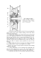
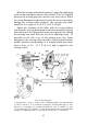
Fig. 59. Steering gear:
1 -steering arm; 2 -case; 3 -lower cover; 4 -adjusting shims of worm bearings;
5 -roller; 6 -worm; 7, 8, 25 -bearings; 9 -plug seal; 10 -filler hole plug; 11 -case
side cover; 12 -bushing; 13 -steering arm shaft; 14 -seal; 15 -washer; 16 -nut;
17 -steering wheel; 18 -column; 19 - steering wheel shaft; 20 -steering arm shaft
bearing; 21 -adjusting screw; 22 -nut-cap; 23 -roller axle; 24 -horn wire
With the steering mechanism removed, adjust the tightening
of the worm bearings by means of the shims 4 (Fig. 59) installed
between the steering gear case and the case lower cover. When
the worm bearings are tightened correctly the force required for
turning the steering wheel (without the steering arm shaft)
should be in a range of 2.2-4.4 N (0.22-0.45 kgf).
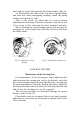
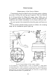
Adjust the meshing of the roller with the worm without
removing the steering mechanism from the automobile (having
only disconnect the drag link from the steering arm) by shifting
the steering arm shaft with the aid of the adjusting screw 21
provided on the side cover of the steering gear case. Upon
adjustment, the steering wheel should be freely turned from the
middle position corresponding to a straight-ahead movement
when a force of 8.8 - 15.7 N (0.9-1.6 kgf) is applied to the
steering wheel.