5 GHz Point to Point 1.
Introduction Introduction Thank you for purchasing the Ubiquiti Networks® airFiber® 5 GHz Point-to-Point 1.0+ Gbps Radio. This Quick Start Guide is designed to guide you through the installation, show you how to access the airFiber Configuration Interface, and explain how to set up an airFiber link.
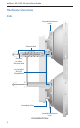
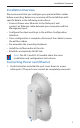
airFiber® AF-5/AF-5U Quick Start Guide Hardware Overview Side Lanyard Attachment Loop Elevation Rod Hex Nut to adjust Elevation Rod Pre-Installed M10 x25 Flanged Bolts Grounding Point Lanyard Attachment Loop Assembled View 2
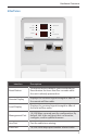
Hardware Overview Interfaces GPS OVERLOAD MASTER LINK 8X REMOTE 6X RESET MANAGEMENT ACT Interface SPEED 4X TO 0.25X LOCAL AUX DATA ACT SPEED Description Reset Button To reset to factory defaults, press and hold the Reset button for more than five seconds while the unit is already powered on. Remote Display Displays the received signal strength in dBm of the remote airFiber radio. Local Display Displays the received signal strength in dBm of the local airFiber radio.
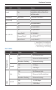
airFiber® AF-5/AF-5U Quick Start Guide LEDs GPS OVERLOAD MASTER LINK 8X REMOTE 6X RESET MANAGEMENT ACT LED GPS Master Link Remote 4 4X to 0.
Hardware Overview LED State Status Local On Displays the received signal strength in dBm of the local airFiber radio. Overload Fast Flash Overload Condition (reserved) – – 8x On 256QAM MIMO 6x On 64QAM MIMO On 16QAM MIMO Long Flash* QPSK MIMO Normal Flash* 1x QPSK xRT™** Short Flash* ¼x QPSK xRT** 4x to 0.
airFiber® AF-5/AF-5U Quick Start Guide Installation Requirements Pre-Assembly Tool • 13 mm wrench Pole-Mounting Tool • 17 mm wrench Other Requirements • Clear line of sight between airFiber radios • Clear view of the sky for proper GPS operation • Vertical mounting orientation • Mounting location with < 0.
Installation Overview Installation Overview We recommend that you configure your paired airFiber radios before mounting. Below is an overview of the installation with specific details in the following instructions: • Connect Power over Ethernet to the Data port, and connect an Ethernet cable between your computer and the Management port. • Configure the device settings in the airFiber Configuration Interface. • Once configuration is complete, disconnect the cables to move the airFiber radios.
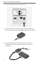
airFiber® AF-5/AF-5U Quick Start Guide 2. Connect an Ethernet cable to the Data port. OVERLOAD GPS MASTER LINK 8X REMOTE 6X RESET MANAGEMENT ACT SPEED 4X to 0.25X LOCAL AUX DATA ACT SPEED 3. Connect the other end of the Ethernet cable from the Data port to the Ethernet port labeled POE on the GigE PoE Adapter. 4. Connect the Power Cord to the power port on the GigE PoE Adapter. Connect the other end of the Power Cord to a power source.
airFiber Configuration airFiber Configuration The instructions in this section explain how to access the airFiber Configuration Interface and configure the following settings: • Wireless Mode Configure one airFiber radio as the Master and the other as the Slave. • Duplex The airFiber radio supports both half-duplex and full‑duplex operation. Half-duplex operation provides more frequency planning options at the cost of higher latency and throughput.
airFiber® AF-5/AF-5U Quick Start Guide 1. Connect an Ethernet cable from your computer to the Management port on the airFiber radio. GPS OVERLOAD MASTER LINK 8X REMOTE 6X RESET MANAGEMENT ACT SPEED 4X to 0.25X LOCAL AUX DATA ACT SPEED 2. Configure the Ethernet adapter on your computer with a static IP address on the 192.168.1.x subnet. 3. Launch your web browser. Type http://192.168.1.20 in the address field and press enter (PC) or return (Mac). 4. The login screen will appear.
airFiber Configuration 5. The Main tab will appear. Click the Tools drop-down and select Link Calculator. This tool will guide you on how to best minimize bandwidth and power/interference issues. Note: If you do not see the Link Calculator, then upgrade the firmware on your airFiber radios. Download the firmware at: downloads.ubnt.com/airfiber 6. Enter the requirements of your link, and then click Calculate.
airFiber® AF-5/AF-5U Quick Start Guide 9. Configure the Wireless Security: a. Select the AES Key Type, HEX or ASCII. b. For the Key field: -- HEX Enter 16 bytes (eight, 16-bit HEX values: 0-9, A-F, or a-f ). You can omit zeroes and use colons, similar to the IPv6 format. Note: The airFiber Configuration Interface supports IPv6 formats excluding dotted quad and "::" (double‑colon) notation. -- ASCII Enter a combination of alphanumeric characters (0-9, A-Z, or a-z). 10. Click Change and then click Apply. 11.
Hardware Installation Hardware Installation The mounting hardware of the airFiber radio can be pre‑assembled before pole-mounting. Mounting Hardware Pre-Assembly 1. Insert two M10x150 Carriage Bolts into the Lower Mount Bracket. 2. Insert two M10x150 Carriage Bolts into the Upper Mount Bracket with Elevation Rod.
airFiber® AF-5/AF-5U Quick Start Guide 3. Attach the Lower Mount Bracket to the I-Bracket using two M8x14 Serrated Flange Bolts. Ensure that the slots face up and securely tighten the bolts.
Hardware Installation 4. Attach the Upper Mount Bracket with Elevation Rod to the I-Bracket using two M8x14 Serrated Flange Bolts. Note: Ensure that the orientation of the Upper Mount Bracket matches the illustration below, with the Elevation Rod on the correct side.
airFiber® AF-5/AF-5U Quick Start Guide 5. Attach the Pole Clamps to the Mount Brackets. a. Slide the slotted hole of each Pole Clamp over one upper and one lower M10x150 Carriage Bolt. b. Place one M10 Serrated Flange Nut on each M10x150 Carriage Bolt.
Hardware Installation 6. Attach the Azimuth Support Brackets together. a. Insert the two M10x100 Carriage Bolts into the Azimuth Support Bracket that has two slotted holes. b. Slide the slotted hole of the other Azimuth Support Bracket over one M10x100 Carriage Bolt. c. Place one M10 Serrated Flange Nut on each M10x100 Carriage Bolt. 7. Check the four Pre-Installed M10x25 Flanged Bolts to ensure that there is a 13 mm gap between each bolt head and its trunnion.
airFiber® AF-5/AF-5U Quick Start Guide Pole-Mounting 1. Attach the Azimuth Support Brackets to the pole just beneath the area where the airFiber radio will be attached. Note: The mounting assembly can accommodate a Ø 38.1 - 101.6 mm (1.5" - 4.0") pole. a. Orient the Azimuth Support Brackets around the pole so it is aimed in the direction of the other airFiber radio. b. Slide the open slot of the Azimuth Support Bracket over the corresponding M10x100 Carriage Bolt. c.
Hardware Installation 2. Attach the mounting assembly to a pole. a. Orient the mounting assembly around the pole so it is aimed in the direction of the other airFiber radio. b. Slide the open slot of each Pole Clamp over the corresponding M10x150 Carriage Bolt. c. Tighten the M10 Serrated Flange Nuts of the M10x150 Carriage Bolts to secure the mounting assembly to the pole.
airFiber® AF-5/AF-5U Quick Start Guide 3. Lift the airFiber radio and align the two lower Pre-Installed M10x25 Flanged Bolts with the slots on the Lower Mount Bracket. Seat the bolts in the slots.
Hardware Installation 4. Align the two upper Pre-Installed M10x25 Flanged Bolts of the airFiber radio next to the slots on the Upper Mount Bracket. Lift the airFiber radio and seat the bolts in the slots.
airFiber® AF-5/AF-5U Quick Start Guide 5. Attach a ground wire: a. Remove the nut from the Grounding Point. b. Attach a ground wire (min. 8 AWG or 10 mm2) to the lug and replace the nut to secure the wire. c. Secure the other end of the ground wire to a grounded mast, pole, tower, or grounding bar. WARNING: Failure to properly ground your airFiber units will void your warranty. Note: The ground wire should be as short as possible and no longer than one meter in length.
Connecting Ethernet Connecting Ethernet 1. Push the button and slide the port cover down to access cable ports. (The port cover cannot be completely removed.) 2. Connect the Data/PoE Ethernet cable: a. Feed an outdoor, shielded CAT6 cable up through the rightmost cable feed slot on the bottom of the port cover. b. Connect the cable to the Data port. c. Create a strain relief for the Ethernet cable by feeding a Cable Tie through the tie slot to the side of the cable. d.
airFiber® AF-5/AF-5U Quick Start Guide 3. Connect the other end of the Ethernet cable from the Data port to the Ethernet port labeled POE on the GigE PoE Adapter. 4. Connect an Ethernet cable from your network to the Ethernet port labeled LAN on the GigE PoE Adapter. 5. Connect the Power Cord to the power port on the GigE PoE Adapter. Connect the other end of the Power Cord to a power source. Note: For added protection, we recommend installing two GigE PoE surge protectors.
Connecting Ethernet Max. 1 m Below is a diagram of a finished installation with recommended surge protectors installed. Ground to Pole, Tower, or Grounding Block: Max.
airFiber® AF-5/AF-5U Quick Start Guide Alignment Tips • To accurately align the airFiber radios for best performance, you MUST align only one end of the link at a time. • For more convenient alignment, you may consider using long‑range scopes (not included) temporarily attached to your airFiber radios. • You may need to use additional hardware to compensate for issues such as the improper orientation of a mounting pole or significant elevation differences between airFiber radios.
Alignment Establishing a Link Adjust the positions of the Master and the Slave to establish a link. Note: The Master must be aimed first at the Slave because the Slave does not transmit any RF signal until it detects transmissions from the Master. 1. Ensure that the following bolts and nuts are loose: • Four Pre-Installed M10x25 Flanged Bolts on the airFiber radio (two on each side) • Four M10 Hex Nuts used to lock the elevation alignment on the Upper Mount Bracket (two on each side) 2.
airFiber® AF-5/AF-5U Quick Start Guide 3. Master Visually aim the Master at the Slave. To adjust the Master's position: a. Rotate the airFiber radio on the pole to align the azimuth. b. Use the hex nut on the Elevation Rod to adjust the elevation. Note: Do NOT make simultaneous adjustments on the Master and Slave. 4. Slave Visually aim the Slave at the Master. To adjust the Slave's position: a. Rotate the airFiber radio on the pole to align the azimuth. b.
Alignment 6. Slave Aim the Slave at the Master to achieve the strongest signal level on the Remote LED Display of the Slave. Note: Values on the LED Displays are displayed in negative (-) dBm. For example, 67 represents a received signal level of -67 dBm. Smaller numerical values indicate stronger received signal levels. For example, a reading of 49 is stronger than a reading of 55. Note: Maximum signal strength can best be achieved by iteratively sweeping through both azimuth and elevation. 7.
airFiber® AF-5/AF-5U Quick Start Guide There are three methods for determining the received signal level: • LED Displays (described above) • airFiber Configuration Interface (webpage) • Audio tone (optional equipment required) Refer to the airFiber AF-5/AF-5U User Guide for instructions on the airFiber Configuration Interface and audio tone methods.
Specifications Specifications airFiber AF-5/AF-5U Dimensions Weight Mount Not Included Mount Included Operating Frequency AF-5 FCC 15.247, 15.407, IC RSS 210 ETSI EN 301 893, EN 302 502 Other Regions AF-5U FCC 15.247, IC RSS 21 ETSI EN 302 502 Other Regions Max Power Consumption 938.4 x 468.4 x 281.4 mm (36.94 x 18.44 x 11.08 in) 11.5 kg (25.35 lb) 16 kg (35.27 lb) 5470 - 5600 MHz, 5650 - 5850 MHz 5470 - 5875 MHz 5470 - 5950 MHz 5725 - 5850 MHz 5725 - 5875 MHz 5725 - 6200 MHz 40 W Power Supply 50V, 1.
airFiber® AF-5/AF-5U Quick Start Guide Receive Sensitivity Spatial Streams Modulation Sensitivity (10 MHz) Sensitivity (20 MHz) FDD Capacity* TDD Capacity* 8x 256QAM -70 dBm -67 dBm 1024 Mbps 512 Mbps 6x 64QAM -77 dBm -74 dBm 768 Mbps 384 Mbps 4x 16QAM MIMO -84 dBm -81 dBm 512 Mbps 256 Mbps 2x QPSK MIMO -90 dBm -87 dBm 256 Mbps 128 Mbps 1x ½ Rate QPSK xRT** -93 dBm -90 dBm 128 Mbps 64 Mbps ¼x ¼ Rate QPSK xRT -95 dBm -93 dBm 32 Mbps 16 Mbps Receive Sensitivity Spatia
Safety Notices Safety Notices 1. Read, follow, and keep these instructions. 2. Heed all warnings. 3. Only use attachments/accessories specified by the manufacturer. WARNING: Do not use this product in location that can be submerged by water. WARNING: Avoid using this product during an electrical storm. There may be a remote risk of electric shock from lightning. Electrical Safety Information 1.
airFiber® AF-5/AF-5U Quick Start Guide Limited Warranty UBIQUITI NETWORKS, Inc (“UBIQUITI NETWORKS”) warrants that the product(s) furnished hereunder (the “Product(s)”) shall be free from defects in material and workmanship for a period of one (1) year from the date of shipment by UBIQUITI NETWORKS under normal use and operation.
Limited Warranty Disclaimer EXCEPT FOR ANY EXPRESS WARRANTIES PROVIDED HEREIN, UBIQUITI NETWORKS, ITS AFFILIATES, AND ITS AND THEIR THIRD PARTY Data, SERVICE, SOFTWARE AND HARDWARE PROVIDERS HEREBY DISCLAIM AND MAKE NO OTHER REPRESENTATION OR WARRANTY OF ANY KIND, EXPRESS, IMPLIED OR STATUTORY, INCLUDING, BUT NOT LIMITED TO, REPRESENTATIONS, GUARANTEES, OR WARRANTIES OF MERCHANTABILITY, ACCURACY, QUALITY OF SERVICE OR RESULTS, AVAILABILITY, SATISFACTORY QUALITY, LACK OF VIRUSES, QUIET ENJOYMENT, FITNESS FO
airFiber® AF-5/AF-5U Quick Start Guide Compliance FCC Changes or modifications not expressly approved by the party responsible for compliance could void the user’s authority to operate the equipment. This device complies with Part 15 of the FCC Rules. Operation is subject to the following two conditions: 1. This device may not cause harmful interference, and 2. This device must accept any interference received, including interference that may cause undesired operation.
Compliance RF Exposure Warning The antennas used for this transmitter must be installed to provide a separation distance of at least 126 cm (AF-5) or 123 cm (AF-5U) from all persons and must not be located or operating in conjunction with any other antenna or transmitter.
airFiber® AF-5/AF-5U Quick Start Guide Deutsch Die Europäische Richtlinie 2002/96/EC verlangt, dass technische Ausrüstung, die direkt am Gerät und/oder an der Verpackung mit diesem Symbol versehen ist, nicht zusammen mit unsortiertem Gemeindeabfall entsorgt werden darf. Das Symbol weist darauf hin, dass das Produkt von regulärem Haushaltmüll getrennt entsorgt werden sollte.
Declaration of Conformity Italiano La direttiva europea 2002/96/EC richiede che le apparecchiature contrassegnate con questo simbolo sul prodotto e/o sull’imballaggio non siano smaltite insieme ai rifiuti urbani non differenziati. Il simbolo indica che questo prodotto non deve essere smaltito insieme ai normali rifiuti domestici.
airFiber® AF-5/AF-5U Quick Start Guide Ελληνική [Greek] ΜΕ ΤΗΝ ΠΑΡΟΥΣΑ UBIQUITI NETWORKS ΔΗΛΩΝΕΙ ΟΤΙ UBIQUITI NETWORKS device, ΣΥΜΜΟΡΦΩΝΕΤΑΙ ΠΡΟΣ ΤΙΣ ΟΥΣΙΩΔΕΙΣ ΑΠΑΙΤΗΣΕΙΣ ΚΑΙ ΤΙΣ ΛΟΙΠΕΣ ΣΧΕΤΙΚΕΣ ΔΙΑΤΑΞΕΙΣ ΤΗΣ ΟΔΗΓΙΑΣ 1995/5/ΕΚ. Magyar [Hungarian] Alulírott, UBIQUITI NETWORKS nyilatkozom, hogy a UBIQUITI NETWORKS device, megfelel a vonatkozó alapvetõ követelményeknek és az 1999/5/EC irányelv egyéb elõírásainak.
www.ubnt.com Support support.ubnt.com Community community.ubnt.com Downloads downloads.ubnt.com © 2013-2014 Ubiquiti Networks, Inc. All rights reserved. Ubiquiti, Ubiquiti Networks, the Ubiquiti U logo, the Ubiquiti beam logo, airFiber, and TOUGHCable are trademarks or registered trademarks of Ubiquiti Networks, Inc. in the United States and in other countries. All other trademarks are the property of their respective owners.