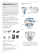
Security Camera Camera Configuration Interface
airCam™ User Guide Table of Contents Table of Contents Chapter 1: Product Overview. . . . . . . . . . . . . . . . . . . . . . . . . . . . . . . . . . . . . . . 1 Package Contents. . . . . . . . . . . . . . . . . . . . . . . . . . . . . . . . . . . . . . . . . . . . . . . . . . . . . . . . . . . . . . . . 1 Installation Requirements . . . . . . . . . . . . . . . . . . . . . . . . . . . . . . . . . . . . . . . . . . . . . . . . . . . . . . . . 1 System Requirements . . . . . . . . . . . . . . . . . . . .
airCam™ User Guide Table of Contents Chapter 8: System Tab . . . . . . . . . . . . . . . . . . . . . . . . . . . . . . . . . . . . . . . . . . . . 16 Device . . . . . . . . . . . . . . . . . . . . . . . . . . . . . . . . . . . . . . . . . . . . . . . . . . . . . . . . . . . . . . . . . . . . . . . . . . 16 Date Settings. . . . . . . . . . . . . . . . . . . . . . . . . . . . . . . . . . . . . . . . . . . . . . . . . . . . . . . . . . . . . . . . . . . . 16 System Accounts. . . . . . . . . . . . . . . . .
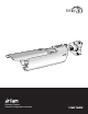
airCam™ User Guide Chapter 1: Product Overview Chapter 1: Product Overview Thank you for purchasing the airCam™, by Ubiquiti Networks. The airCam is a professional-grade H.264 IP indoor/outdoor camera that features 1MP/HDTV 720p/30 FPS capabilities and works in low-light and night-viewing environments. Hardware Overview Front Sun Shade This User Guide is designed to provide intructions about installation of the airCam and to provide details about how to set up and use the airCam configuration interface.
airCam™ User Guide Chapter 2: Installation Chapter 2: Installation 4. Unscrew the Indoor Ethernet Port Cover on the back of the airCam. The installation process is different depending on if you are mounting the camera indoors or outdoors. Follow the instructions for the installation that you are performing. Indoor Installation 1. Remove the screw and knob that connect the Mounting Bracket Base to the camera attachment by turning the knob counter-clockwise. Mounting Bracket Base 5.
airCam™ User Guide Chapter 2: Installation 10. Insert the Mounting Bracket into the airCam until a click is heard to confirm a secure installation. 2. Connect the Ethernet cable to the Ethernet port. Continue to “Connecting the Power” on page 4. Outdoor Installation Important: The ideal outdoor location for mounting the airCam would be under an overhang/eave that shelters the camera.
airCam™ User Guide 7. Secure the wall-mount bracket to the wall by inserting the self tapping screws into the anchors. Note: There are three recessed areas for the Ethernet cable on the Mounting Bracket Base. Place the Ethernet cable in the recessed area that will be nearest to your power source. Chapter 2: Installation 2. Connect an Ethernet cable from your LAN to the Ethernet port labeled LAN on the PoE Adapter. 3. Connect the power cord to the power port on the PoE Adapter.
airCam™ User Guide Chapter 2: Installation 4. The login screen will appear. Enter ubnt in the Username and Password fields and click Login. 5. The Main screen will appear and you should see a live stream of video from the airCam. Adjusting the Camera View Side to Side Up and Down Hardware installation is complete. For details on using the airVision software or the Camera Configuration Interface, refer to the documentation included on the CD‑ROM. Ubiquiti Networks, Inc.
airCam™ User Guide Chapter 3: Using the airCam Configuration Interface The software that comes with your airCam has a browserbased interface for easy configuration and management. To access the interface, perform the following steps: 1. Launch your Web browser and type http://192.168.1.20 in the address field and press Enter (PC) or Return (Mac). 2. The login screen will appear. Enter the admin name and password in the appropriate fields and click Login.
airCam™ User Guide Chapter 4: Main Tab The Main tab displays airCam status/statistical information and provides video and client monitoring links. Chapter 4: Main Tab Monitor Live View Status Device Name Displays the customizable name (ID) of the airCam. The Device Name can be modified on the System tab. Version Displays the version of the airVision software installed. Uptime This is the total time the airCam has been running since last power up (reboot) or software upgrade.
airCam™ User Guide Camera Controls Chapter 4: Main Tab Netmask Displays the airCam’s Netmask when operating in DHCP Client mode. It is assigned automatically by the DHCP server, which also assigns the IP address to the airCam. Gateway Displays the airCam’s gateway when operating in DHCP Client mode, which is assigned automatically by the DHCP server. Primary/Secondary DNS IP Domain Name System (DNS) is an Internet “phone book” which translates domain names to IP addresses.
airCam™ User Guide Chapter 5: Video Tab Chapter 5: Video Tab The Video tab allows you to configure basic Video Settings including the Bit Rate and Quality and Advanced Settings including Resolution, Frame Rate, IP Interval, Refresh Frequency, MJPEG Quality and Image Rotation settings for the airCam. Video Settings Bit Rate, Kbit/s This option allows the selection of the bit rate in kilobits per second. Options include 16, 64, 128, 256, 512, 1024, 1536, 2048, 4096.
airCam™ User Guide Chapter 6: Network Tab Chapter 6: Network Tab The Network tab covers the configuration of the Network Settings, VLAN Network Settings, Firewall Settings, Static Routes, TCP Explicit Congestion Notification and Advanced Ethernet Settings. Network Settings IP Address The airCam can be set for static IP or can be set to obtain an IP address from the DHCP server it is connected to.
airCam™ User Guide MTU Enter the size (in bytes) of the largest protocol data unit the layer can pass on. When using slow links, large packets can cause some delays thereby increasing lag and latency. By default, the MTU is set to 1500 bytes. Auto IP Aliasing Automatically generates an IP Address for the corresponding LAN interface if enabled. The generated IP address is a unique Class B IP address from the 169.254.X.Y range (Netmask 255.255.0.
airCam™ User Guide Static Routes Chapter 6: Network Tab Advanced Ethernet Settings Static routing rules can be added manually to the System Routing Table, allowing the specification of target IP address(es) that may pass through a determined gateway. Static Routes functionality can be enabled by clicking Configure. For each entry, specify a valid Target Network IP, Netmask, Gateway IP, enter a Comment (optional), and select the ON check box, in order to enable this rule.
airCam™ User Guide Chapter 7: Services Tab The Services tab covers the configuration of system management services including Ping Watchdog, SNMP Agent, Web Server, SSH Server, Telnet Server, NTP Client, Dynamic DNS, and System Log. Ping Watchdog Ping Watchdog sets the airCam to continuously ping a user defined IP address (it can be the Internet gateway for example). If it is unable to ping under the user defined constraints, the airCam will automatically reboot.
airCam™ User Guide Chapter 7: Services Tab SNMP Agent SSH Server Simple Network Monitor Protocol (SNMP) is used in network management systems to monitor network‑attached devices for conditions that warrant administrative attention. The airCam contains an SNMP agent which allows it to communicate to SNMP manage applications for network provisioning.
airCam™ User Guide Chapter 7: Services Tab Dynamic DNS Enable Dynamic DNS Select this check box to enable Dynamic DNS service for the airCam. Dynamic DNS is a network service providing which allows real-time notification to the DNS Server of any changes occurring in the airCam’s IP setting, there by allowing access to the airCam through a Domain Name even if the airCam’s IP address has changed. Host Name Defines the Dynamic DNS Host Name. A large list of Dynamic DNS services is available here.
airCam™ User Guide Chapter 8: System Tab Chapter 8: System Tab Date Settings The System tab contains controls for airCam Device Settings, Date Settings, System Accounts, Configuration Management and Device Maintenance. Device Device Name (Host name) is the system wide device identifier. It is reported by the SNMP Agent to authorized management stations. Device Name will be represented in popular Router Operating Systems registration screens and discovery tools.
airCam™ User Guide System Accounts In this section you can modify the administrator password to protect your device from unauthorized configuration. The default administrator’s password should be changed on the very first system setup: Chapter 8: System Tab Note: The new configuration is active after clicking Apply and the system reboot cycle is completed. The previous system configuration is deleted after you click Apply.
airCam™ User Guide Chapter 8: System Tab Tools Ping The Ping tool is used to check the preliminary link quality and packet latency estimation between two network devices using ICMP packets. Network Ping Select Destination IP A remote system IP can be selected from the list which is generated automatically or can be specified manually. Packet Count Enter the number of packets to send for the ping test. Packet Size The size of the ICMP packets can be specified in this field.
airCam™ User Guide Appendix A: Specifications Appendix A: Specifications Dimensions Network Security Multiple user access levels with password protection, User access log Supported Protocols IPv4/v6, HTTP, UPnP, DNS, NTP, RTSP, DHCP, TCP, UDP, IGMP, RTCP, ICMP, ARP 158 x 61.5 x 58.5 mm (without mounting arm) 264 x 61.5 x 58.
airCam™ User Guide Appendix B: Safety Notices Appendix B: Safety Notices 1. Read, follow, and keep these instructions. 2. Heed all warnings. 3. Only use attachments/accessories specified by the manufacturer. WARNING: Do not use this product in location that can be submerged by water. WARNING: Avoid using this product during an electrical storm. There may be a remote risk of electric shock from lightning. Electrical Safety Information 1.
airCam™ User Guide Appendix C: Warranty General Warranty UBIQUITI NETWORKS, Inc (“UBIQUITI NETWORKS”) represents and warrants that the Products furnished hereunder shall be free from defects in material and workmanship for a period of one (1) year from the date of shipment by UBIQUITI NETWORKS under normal use and operation. UBIQUITI NETWORKS sole and exclusive obligation under the foregoing warranty shall be to repair or replace, at its option, any defective Product that fails during the warranty period.
airCam™ User Guide Appendix D: Compliance Information Installer Compliance Responsibility Devices must be professionally installed and it is the professional installer’s responsibility to make sure the device is operated within local country regulatory requirements.
airCam™ User Guide RoHS/WEEE Compliance Statement Appendix D: Compliance Information detallada sobre la eliminación segura de su aparato usado, consulte a las autoridades locales, al servicio de recogida y eliminación de residuos de su zona o pregunte en la tienda donde adquirió el producto. Français European Directive 2002/96/EC requires that the equipment bearing this symbol on the product and/ or its packaging must not be disposed of with unsorted municipal waste.
airCam™ User Guide Appendix E: Declaration of Conformity Česky [Czech] UBIQUITI NETWORKS tímto prohla uje, e tento UBIQUITI NETWORKS device, je ve shod se základními po adavky a dal ími p íslu n mi ustanoveními sm rnice 1999/5/ES. Dansk [Danish] Undertegnede UBIQUITI NETWORKS erklærer herved, at følgende udstyr UBIQUITI NETWORKS device, overholder de væsentlige krav og øvrige relevante krav i direktiv 1999/5/EF.
airCam™ User Guide Appendix F: Contact Information Appendix F: Contact Information Ubiquiti Networks Support Ubiquiti Support Engineers are located in the U.S. and Europe and are dedicated to helping customers resolve software, hardware compatibility, or field issues as quickly as possible. We strive to respond to support inquiries within a 24 hour period. Email: support@ubnt.com Phone: 408-942-1153 (9 a.m. - 5 p.m. PST) Online Resources Wiki Page: www.ubnt.com/wiki Support Forum: www.ubnt.