
User guide

11
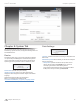
Chapter 6: Network Tab airCam
™
User Guide
Ubiquiti Networks, Inc.
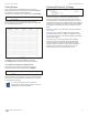
MTU Enter the size (in bytes) of the largest protocol data unit
the layer can pass on. When using slow links, large packets can
cause some delays thereby increasing lag and latency. By default,
the MTU is set to 1500 bytes.
Auto IP Aliasing Automatically generates an IP Address for
the corresponding LAN interface if enabled. The generated IP
address is a unique Class B IP address from the 169.254.X.Y range
(Netmask 255.255.0.0) which is intended for use within the same
network segment only. Auto IP always starts with 169.254.X.Y
while X and Y are last 2 digits from the MAC address of the device
(i.e. if the MAC is 00:15:6D:A3:04:FB, Generated unique Auto IP
will be 169.254.4.251).
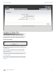
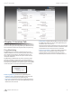
IP Aliases IP aliases for the internal and external network
interface can be configured. IP Aliases can be specified using the
LAN IP Aliases configuration window which is opened when you
click Configure.
• IP The alternative IP address for the LAN interface, which can
be used for the routing or device management purposes.
• Netmask The network address space identifier for the
particular IP Alias.
• Comments Field used for a brief description of the purpose of
the IP Alias.
• Enabled Enables or disables the particular IP Alias. All added
IP Aliases are saved in the system configuration file, however
only the enabled IP Aliases are active on the device.
Newly-added IP Aliases can be saved by click the Save button
or discarded by clicking the Cancel button in the LAN IP Aliases
configuration window.
VLAN Network Settings
Enable VLAN Enable this this feature to allow the management
of the device to only occur on a specific management VLAN.
VLAN ID The VLAN ID is a unique value assigned to each VLAN
at a single device; every VLAN ID represents a different Virtual
Network. VLAN ID range values between 2 and 4094 are allowed.
Only one VLAN ID is allowed per device.
VLAN Network Defines which network interface will be
assigned to the specified VLAN ID.
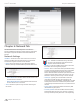
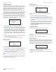
Firewall Settings
Firewall functionality can be enabled by clicking Enable Firewall.
Firewall rules can be configured, enabled or disabled using the
Firewall configuration window which opens when you click
Configure.
Firewall entries can be specified by using the following criteria:
Action Allows two specific firewall rules: ACCEPT or DROP. By
enabling ACCEPT the packets can pass the firewall unmodified.
When choosing DROP, the packets are denied passage through
the firewall and no response is sent.
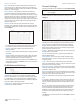
Interface The interface where filtering of the incoming/passing-
through packets are processed.
IP Type Sets which particular L3 protocol type (IP, ICMP, TCP,
UDP) should be filtered.
Source IP/Mask The source IP of the packet (specified within
the packet header), usually it is the IP of the host system which
sends the packets.
Src Port The source port of the TCP/UDP packet (specified
within the packet header), usually it is the port of the host system
application which sends the packets.
Destination IP/Mask The destination IP of the packet (specified
within the packet header), usually it is the IP of the system which
the packet is addressed to.
Dst Port The destination port of the TCP/UDP packet (specified
within the packet header), usually it is the port of the host system
application which the packet is addressed to.
Comment Field used to enter a brief description of the firewall
entry.
On Enables or disables the effect of the particular firewall entry.
All added firewall entries are saved in system configuration file,
however only the enabled firewall entries will be active on the
device.
Not Can be used for inverting the Source IP/mask, Source Port,
Destination IP/mask and Destination Port filtering criteria (i.e.
if not is enabled for the specified Destination Port value 443,
the filtering criteria will be applied to all the packets sent to any
Destination Port except the 443 which is commonly used by
HTTPS).
Click Save to save your firewall entries or click Cancel to discard
your changes.