5 GHz, 23 dBi airMAX® CPE with InnerFeed® Technology Model: LBE-5AC-23
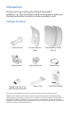
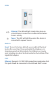
Introduction Thank you for purchasing the Ubiquiti Networks® LiteBeam™ ac. This Quick Start Guide is designed to guide you through installation and also includes warranty terms. Package Contents Antenna Feed Feed Receiver Center Reflector Panel Ball Joint Mount Side Reflector Panels (Qty. 2) Metal Strap 5 GHz, 23 dBi airMAX® CPE with InnerFeed® Technology Model: LBE-5AC-23 Gigabit PoE (24V, 0.
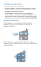
Installation Requirements • 7 mm socket wrench or screwdriver • Shielded Category 5 (or above) cabling should be used for all wired Ethernet connections and should be grounded through the AC ground of the PoE. We recommend that you protect your networks from harmful outdoor environments and destructive ESD events with industrial‑grade, shielded Ethernet cable from Ubiquiti Networks. For more details, visit www.ubnt.
Hardware Overview Bottom View Technology LEDs Reset Button Ethernet Port Antenna Feed Reflector Assembly Securing Arms Port Cover Feed Receiver Lock Nut Ball Joint Mount
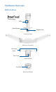
LEDs Ethernet The LED will light steady blue when an active Ethernet connection is made and flash when there is activity. Power The LED will light blue when the device is connected to a power source. Button Reset To reset to factory defaults, press and hold the Reset button for more than 10 seconds while the LiteBeam ac is already powered on. Alternatively, the LiteBeam ac may be reset remotely via a Reset button located on the bottom of the Gigabit PoE adapter.
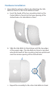
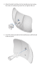
Hardware Installation 1. Assemble the antenna reflector by attaching the Side Reflector Panels to the Center Reflector Panel: a. Insert the heads of the two mounting studs on the Center Reflector Panel into the large opening of the slotted holes of a Side Reflector Panel. b. Slide the Side Reflector Panel down until the top edges of the panels align. The Side Reflector Panel is captured when both heads of the mounting studs are positioned over the narrow opening of the slotted holes. c.
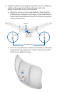
2. Hold the reflector assembly by hand (do not use a tabletop or flat surface) and insert the Feed Receiver into the reflector assembly to secure the panels: a. Align the arrows on the Center Reflector Panel and the Feed Receiver, and insert both edges of the Side Reflector Panels and Center Reflector Panels into the Securing Arms of the Feed Receiver. Arrows Securing Arms b.
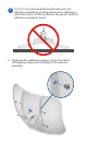
WARNING: Do not install the Feed Receiver into the reflector assembly by pushing down onto a tabletop or other flat surface as this can deform the panels. Hold the reflector assembly by hand. 3. (Optional) For additional support, attach four M3x4 self‑tapping screws (not included) to the antenna assembly.
4. Attach the Ball Joint Mount to the Feed Receiver by turning the lock nut clockwise by hand. Do not tighten the nut. 5. Insert the Antenna Feed into the Feed Receiver until the feed locks into place.