induction introduction ‘Thank you for purchasing the Ambiguity Networks® SolarBears™ This Quick Start Guide is designed to guide you through installation and also includes warranty terms. Package Contents The Solar Beam is available in three models: 58-700-1 single panel), SB-700-2 {two panels), SB-700-3 {three panels).
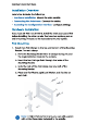
Solar Bear Quick Start Slued Hardware Overview Electronics Compartment The compartment is located on the back of the main solar panel. CROWD Fuse Lan 2 ogi bet PY Connects to PY cabling, Extravagant Optional Connect an enema batter and the Enchilada NIC Theorist, Tha programmable charge voltage i 3512 308 (power-on default FEA or 27.2 (fell. 2DC Out Optional: You can connect a 24VDC device [40W raxirmum}, Enable 2400 output through the Configuration Interface.
Hardware Overview Ep ho Dual RIS ports support 107100 Ethernet and passive 24V FoF output (40W maximum). Enable PoE output through the Configuration interface. LAN 1-2 Note: You can connect your load(s) to either the 24V0C Out or LAN ports, or all ports, as long as the total power consumption is less than or equal to 40W.
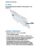
Solar Bear Quick Start Slued PY Cabling Every solar panel has two Attached PV Cables, positive and negative Ar ached PV Cables installation Requirements » Hatchet wrench with 13 and 17 mm caskets * 13 mm combination wrench * 3 mim hex wrench (Splice iit for $B-700-2 or SB-700-2 only} + Shielded Category 5 {or above) cabling with drain wire should be used for all wired Ethernet connections and should be properly grounded to the parthenogenesis ground.
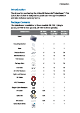
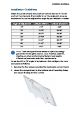
Installation Sidelines installation Guidelines Orient the panel towards the south {or towards the north fin the sou them hemisphere). If you prefer to set the angle just once, we recommend to use the adjustment angle for your latitude In winter. Lei <13° <30° 207 1aa0n 00° 30° 0-27 AEN aar JE E00 Eid 24-417 SFY ann 4-477 FOR bid 47° »B0° Note: These are approximate values to optimize energy generation in the given season.
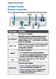
Solar Bear Quick Start Slued Installation Overview Installation includes the following: = Hardware installation Mount the solar panel(s]. = Connecting the Solarium Connect the cables. = Accessing the Configuration Interface Configure settings. Hardware Installation If you have SB-700-2 or 58-7003, install the main solar panel first before installing the other panels. You have two options, pole or wall mounting. Proceed to the instructions for your option. Pole Mounting 1.
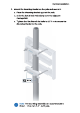
Hardware Installation 2. Mount the Mounting Bracket on the pole and secure it. 2. Place the Mounting Bracket against the pole. b. Slide the slot of each Pole Clamp over the adjacent Carriage Bolt. © Tighten the Hex Nuts of the bolts to 25 Nom to secure the Counting Bracket to the pole. Note: The mounting assembly can accommodate a #381 -101.6 mm (1.5 407 pole.
Solar Bear Quick Start Slued If you added the third Pole Clamp for additional support In high-wind environments, then the finished mounting assembly with three Pole Clamps will look like this:
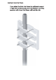
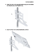
Hardware Installation 3. Attach the Strut to the Mounting Racket using two Flo Washers and Bracket Screws. Hand-tighten only, 4 Insert the Panel into the Mounting Bracket and Strut.
Solar Bear Quick Start Slued 5. Attach the Panel to the Mounting Bracket and Strut using four Flat Washers and Bracket Screws. Hand-tighten only. 6. Adjust the angle of the Panel based on your latitude (refer to the installation Guidelines section on page 51.
Connecting the Solar Beam Connecting the Solar Beam Before you begin, unscrew the thumbscrews to remove the port cover, When you have finished your connections, hand tighten the grommets and replace the port cover, Connecting to an External Battery {Optional} You can use flexible conduit or an optional cable gland {not Included) for your connection to sn external battery, 1.
Solar Bear Quick Start Slued 2. Feed a DC cable (not included, maximum size: 14AWG) through the hole and wire to the Ext Bart terminal block, WARNING: We strongly recommend that you add an appropriate DC breaker (interrupter) between the Ext Butterfat terminal block and external battery to increase safety during Installation or maintenance, Suggested breaker rating: 30VDLM0A, 3. Wire the other end to an external battery. 4.
Connecting the Solar Beam Connecting to the DC Output (Optional) Note: Ensure that your network device supports the supplied voltage, 1. Remove the Fuse to disable the DC output. 2. Feed the included DC Cable through the grommet and wire it ta the 24V OC Outskirt terminal block, 3. Wire the other end of the table to 8 network device that supports the supplied voltage. 4. Replace the Fuse to enable the DC output.
Solar Bear Quick Start Slued Connecting Ethernet Note: You are using Tough Cable, we recommend attaching the TOUGH able Connector(s) after you Insert the cables) into the grommet, 1. Rotate the grommet cover counterclockwise to remove It.
Connecting the Solar Beam 3. Slide the grommet cover over the Theme cable, and then fit the grommet over the cable. Note: You are connecting two Ethernet cables, then use the double-cable grommet (per-installed). If you correcting only & single Ethernet cable, then use the included Single-Cole Grommet instead. 4, Connect the Ethernet cables) to the LAN portly. 5. Replace the grommet and rotate the grommet cover dock wise 0 secure it 6 Connect the other ends of the cables to FoF network devices.
Solar Bear Quick Start Slued Connecting PV Cabling instructions for SB-700-1 Connect the Attached PV Cables to its electronics compartment. 1. Feed the At ached PV Cables through the grommet. 2. Wire the positive FY Cable to the positive input of the PV terminal block, WARNING: The PV Cables carry electricity any time the panel Is exposed to light. You must wire a single cable at a time because they could short i you connect them at the same time.