802.
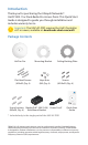
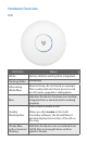
Introduction Thank you for purchasing the Ubiquiti Networks® UniFi® 802.11ac Dual-Radio Pro Access Point. This Quick Start Guide is designed to guide you through installation and includes warranty terms. Important: The UAP-AC-PRO requires the UniFi Controller v4.7 or newer, available at: downloads.ubnt.com/unifi Package Contents UniFi ac Pro Flat Head Screws (M3x50, Qty. 4) Mounting Bracket Keps Nuts (M3, Qty. 4) Ceiling Backing Plate Screws (M2.9x20, Qty. 4) 802.
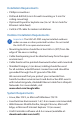
Installation Requirements • Phillips screwdriver • Drill and drill bit (6 mm for wall-mounting or 3 mm for ceiling‑mounting) • Optional: Drywall or keyhole saw (to cut 18 mm hole for Ethernet cable feed) • Cat5/6 UTP cable for indoor installations Outdoor Installation Requirements Important: The UAP-AC-PRO may be installed outdoors under an eave or other protected location. Do not install the UniFi AP in an open environment.
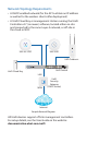
Network Topology Requirements • A DHCP-enabled network (for the AP to obtain an IP address as well as for the wireless clients after deployment) • A UniFi Cloud Key or management station running the UniFi Controller v4.
Hardware Overview LED LED Color Status White Factory default, waiting to be integrated. Flashing White Initializing. Alternating White/Blue Device is busy; do not touch or unplug it. This usually indicates that a process such as a firmware upgrade is taking place. Blue Indicates the device has been successfully integrated into a network and is working properly. This is used to locate an AP. Quickly Flashing Blue When you click Locate in the UniFi Controller software, the AP will flash.
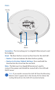
Ports Security Slot Secondary Port Main Port Reset Button Secondary The Secondary port is a Gigabit Ethernet port used for bridging. Reset The Reset button serves two functions for the UniFi AP: • Restart Press and release the Reset button quickly. • Restore to Factory Default Settings Press and hold the Reset button for more than five seconds. Main The Main port is a Gigabit Ethernet port used to connect the power and should be connected to the LAN and DHCP server.
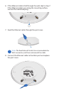
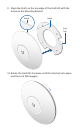
Hardware Installation The UniFi AP can be mounted on the wall or ceiling. Perform the steps for the appropriate installation: Wall Mount 1. Position the Mounting Bracket at the desired location on the wall with the Arrow pointing up. 2. Mark the four mounting holes, and use a 6 mm drill bit to drill the holes. Arrow 3. If your Ethernet cable feeds through the wall, cut or drill a circle approximately 18 mm in diameter (as shown below). Then feed the CAT5/6 cable through the hole.
4. Insert the Screw Anchors into the 6 mm holes. Secure the Mounting Bracket to the wall by inserting the Screws into the anchors. 5. Remove the rubber port cover from the UniFi AP.
6. If the Ethernet cable is fed through the wall, skip to step 7. If the Ethernet cable runs along the mounting surface, remove the cable feed plug. 7. Feed the Ethernet cable through the port cover. Note: The feed hole will stretch to accommodate the RJ45 connector, and then seal around the cable. 8. Connect the Ethernet cable to the Main port and replace the port cover.
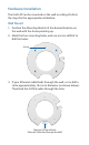
9. Align the Notch on the top edge of the UniFi AP with the Arrow on the Mounting Bracket. Notch Arrow Lock Tab 10. Rotate the UniFi AP clockwise until the tabs lock into place and the Lock Tab engages.
Ceiling Mount 1. Remove the ceiling tile. 2. Place the Ceiling Backing Plate in the center of the ceiling tile. Mark the four mounting screw holes and a 18 mm hole for the Ethernet cable feed. 18 mm Hole for Ethernet Cable Feed 3. Use a 3 mm drill bit to drill the screw holes, and cut or drill the hole for the Ethernet cable feed.
4. Insert the Flat Head Screws through the Mounting Bracket, ceiling tile, and Ceiling Backing Plate. Fasten the screws using the Keps Nuts. Then feed the Ethernet cable through the tile and bracket.
5. Remove the port cover from the UniFi AP, and then feed the Ethernet cable through the port cover. Note: The feed hole will stretch to accommodate the RJ45 connector, and then seal around the cable. 6. Connect the Ethernet cable to the Main port and replace the port cover.
7. Align the Notch on the top edge of the UniFi AP with the Arrow on the Mounting Bracket. Lock Tab Arrow Notch 8. Rotate the UniFi AP clockwise until the tabs lock into place and the Lock Tab engages. 9. Set the ceiling tile back into place.
Powering the UniFi AP The UAP-AC-PRO features auto-sensing 802.3af/802.3at PoE support and can be powered by any of the following: • Ubiquiti Networks UniFi Switch • 802.3af/802.3at PoE+ compliant switch • Ubiquiti Networks Gigabit PoE Adapter (48V, 0.5A) The single-pack of the UAP-AC-PRO includes one Gigabit PoE adapter. For multi-pack units, PoE adapters or a UniFi Switch may be purchased separately.
Connecting to a PoE Adapter 1. Connect the Ethernet cable from the UniFi AP to the POE port of the Gigabit PoE adapter. 2. Connect an Ethernet cable from your LAN to the LAN port of the Gigabit PoE adapter. 3. Connect the Power Cord to the adapter, and then plug the Power Cord into a power outlet. Mounting the PoE Adapter (Optional) 1. Remove the PoE Mounting Bracket from the adapter, place the bracket at the desired location, and mark the two holes. 2.
Software Installation Download and install the latest version of the UniFi Controller software at: downloads.ubnt.com/unifi Launch the software and follow the on-screen instructions. Step-by-step instructions are available in the User Guide located on our website: documentation.ubnt.com/unifi After you have installed the software and run the UniFi Installation Wizard, a login screen will appear for the UniFi Controller management interface.
Specifications UAP-AC-PRO 196.7 x196.7 x 35 mm (7.74 x 7.74 x 1.38") Dimensions Weight with Mounting Kit Networking Interface Buttons 350 g (12.35 oz) 450 g (15.87 oz) (2) 10/100/1000 Ethernet Ports Reset Max. Power Consumption Power Method 9W PoE 802.3af/802.3at Power Supply 48V, 0.5A Gigabit PoE Adapter* Max. TX Power 2.4 GHz 5 GHz 22 dBm 22 dBm Antennas (3) Dual-Band Antennas, 3 dBi each Wi-Fi Standards 802.
Safety Notices 1. Read, follow, and keep these instructions. 2. Heed all warnings. 3. Only use attachments/accessories specified by the manufacturer. WARNING: Do not use this product in location that can be submerged by water. WARNING: Avoid using this product during an electrical storm. There may be a remote risk of electric shock from lightning. Electrical Safety Information 1. Compliance is required with respect to voltage, frequency, and current requirements indicated on the manufacturer’s label.
Limited Warranty UBIQUITI NETWORKS, Inc (“UBIQUITI NETWORKS”) warrants that the product(s) furnished hereunder (the “Product(s)”) shall be free from defects in material and workmanship for a period of one (1) year from the date of shipment by UBIQUITI NETWORKS under normal use and operation.
Disclaimer EXCEPT FOR ANY EXPRESS WARRANTIES PROVIDED HEREIN, UBIQUITI NETWORKS, ITS AFFILIATES, AND ITS AND THEIR THIRD PARTY DATA, SERVICE, SOFTWARE AND HARDWARE PROVIDERS HEREBY DISCLAIM AND MAKE NO OTHER REPRESENTATION OR WARRANTY OF ANY KIND, EXPRESS, IMPLIED OR STATUTORY, INCLUDING, BUT NOT LIMITED TO, REPRESENTATIONS, GUARANTEES, OR WARRANTIES OF MERCHANTABILITY, ACCURACY, QUALITY OF SERVICE OR RESULTS, AVAILABILITY, SATISFACTORY QUALITY, LACK OF VIRUSES, QUIET ENJOYMENT, FITNESS FOR A PARTICULAR PUR
Note Some countries, states and provinces do not allow exclusions of implied warranties or conditions, so the above exclusion may not apply to you. You may have other rights that vary from country to country, state to state, or province to province. Some countries, states and provinces do not allow the exclusion or limitation of liability for incidental or consequential damages, so the above limitation may not apply to you.
Industry Canada CAN ICES-3(A)/NMB-3(A) This Class A digital apparatus complies with Canadian ICES-003. To reduce potential radio interference to other users, the antenna type and its gain should be so chosen that the equivalent isotropically radiated power (e.i.r.p.) is not more than that permitted for successful communication. This device complies with Industry Canada licence-exempt RSS standard(s). Operation is subject to the following two conditions: 1. This device may not cause interference, and 2.
RF Exposure Warning The antennas used for this transmitter must be installed to provide a separation distance of at least 20 cm from all persons and must not be located or operating in conjunction with any other antenna or transmitter, except as listed for this product’s certification.
RoHS/WEEE Compliance Statement English European Directive 2002/96/EC requires that the equipment bearing this symbol on the product and/or its packaging must not be disposed of with unsorted municipal waste. The symbol indicates that this product should be disposed of separately from regular household waste streams. It is your responsibility to dispose of this and other electric and electronic equipment via designated collection facilities appointed by the government or local authorities.
Español La Directiva 2002/96/CE de la UE exige que los equipos que lleven este símbolo en el propio aparato y/o en su embalaje no deben eliminarse junto con otros residuos urbanos no seleccionados. El símbolo indica que el producto en cuestión debe separarse de los residuos domésticos convencionales con vistas a su eliminación.
Declaration of Conformity Česky [Czech] UBIQUITI NETWORKS tímto prohlašuje, že toto UBIQUITI NETWORKS zařízení, je ve shod se základními požadavky a dalšími příslušnými ustanoveními směrnice 1999/5/ES. Dansk [Danish] Hermed, UBIQUITI NETWORKS, erklærer at denne UBIQUITI NETWORKS enhed, er i overensstemmelse med de væsentlige krav og øvrige relevante krav i direktiv 1999/5/EF.
Malti [Maltese] Hawnhekk, UBIQUITI NETWORKS, tiddikjara li dan il-mezz UBIQUITI NETWORKS huwa konformi mar-rekwiżiti essenzjali u dispożizzjonijiet rilevanti oħrajn ta ‘Direttiva 1999/5/EC. Norsk [Norwegian] Herved UBIQUITI NETWORKS, erklærer at denne UBIQUITI NETWORKS enheten, er i samsvar med de grunnleggende kravene og andre relevante bestemmelser i direktiv 1999/5/EF.