Networked Serial Interface Model: mPort-S
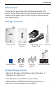
Introduction Introduction Thank you for purchasing the Ubiquiti Networks mFi™ mPort™ Serial. The mPort Serial includes the mFi Controller software that allows you to control your machines using your web browser. Package Contents mPort Serial Wall-Mount Bracket PoE Adapter and Power Cord Antenna mPort Serial Model: mPort-S Terminal Block Screws (Qty. 4) Anchors (Qty.
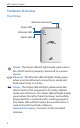
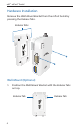
mFi™ mPort™ Serial Hardware Overview Front View Antenna Connector Power LED Ethernet LED Status LED Power The Power LED will light steady green when the mPort Serial is properly connected to a power source. Ethernet The Ethernet LED will light steady green when an active Ethernet connection is made and flash when there is activity. Status The Status LED will light yellow when the mPort Serial is first powered on in factory default mode out of the box.
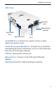
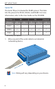
Hardware Overview Side View Ethernet Port Wall-Mount Bracket Serial DB9 Port Serial TB Port USB Port Serial DB9 Port Connects to a switch, router, or other device for remote access. Serial TB (Terminal Block) Port Connects to an industrial networking device for automation, such as script execution from the mFi Controller software. USB Port Reserved for future use. Ethernet Port Connects to the POE port of the PoE Adapter. Wall-Mount Bracket Wall-mounting is optional.
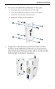
mFi™ mPort™ Serial Hardware Installation Remove the Wall-Mount Bracket from the mPort Serial by pressing the Release Tabs. Release Tabs Wall-Mount (Optional) 1. Position the Wall-Mount Bracket with the Release Tabs on top.
Hardware Installation 2. To secure the Wall-Mount Bracket to the wall: a. Use a pencil to mark the holes on the wall. b. Use a 6 mm drill bit to drill the holes in the wall. c. Insert the four Anchors into the wall. d. Insert the Screws into the anchors. 3. Angle the mPort Serial so that the notches on the bottom of the Wall‑Mount Bracket are inserted into the mPort Serial. Then press the mPort Serial into the Release Tabs and snap it into place.
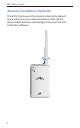
mFi™ mPort™ Serial Antenna Installation (Optional) The mPort Serial uses the internal antenna by default. If you want to use an external antenna, then attach the included Antenna and configure its use in the mFi Controller software.
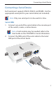
Connecting a Serial Device Connecting a Serial Device Each serial port supports RS232, RS422, and RS485. Use the appropriate serial port for your serial cable (not included). Note: Only one serial port can be used at a time. Serial DB9 1. Connect one end of the serial cable to the console port of the switch, router, or other device. Note: A null modem may be needed; refer to the User Guide on the CD-ROM for more information. 2.
mFi™ mPort™ Serial Serial TB The Serial TB port is labeled for RS485 pinout. The table lists the pinouts for RS232, RS422, and RS485. For more information, refer to the User Guide on the CD-ROM. Function RX TX R+ T- Ground Pinout R- RS232 ✓ T+ RS422 ✓ ✓ ✓ ✓ * RS485 ✓ ✓ ✓ ✓ * ✓ G ✓ * Technically not needed. 1. Wire one end of the serial cable to an industrial networking device. Note: Wiring will vary depending on your device.
Connecting a Serial Device 2. Wire the other end of the serial cable to the Terminal Block included with the mPort Serial. 3. Insert the Terminal Block into the Serial TB port of the mPort Serial.
mFi™ mPort™ Serial Connecting Ethernet and Power 1. Connect an Ethernet cable to the Ethernet port on the mPort Serial. 2. Connect the other end of the Ethernet cable to the Ethernet port labeled POE on the PoE Adapter.
Connecting Ethernet and Power 3. Connect an Ethernet cable from your LAN to the Ethernet port labeled LAN on the PoE Adapter. Note: Wi-Fi settings for the mPort Serial can be configured via LAN or by connecting an Ethernet cable directly from your computer to the LAN port on the PoE Adapter. For details, refer to Accessing the mPort Configuration Portal on page 19. 4. Connect the power cord to the power port on the PoE Adapter. Connect the other end of the power cord to a power outlet.
mFi™ mPort™ Serial Software Download and Installation For local mFi Controller installations, the mFi Controller software is installed just once when you initially create a mFi network. It is not necessary to go through the software installation process every time you add another mFi device. Note: If you are using the cloud, there is no need to install the mFi Controller software locally. Skip to Accessing the mPort Configuration Portal on page 19.
Software Download and Installation 2. Click Continue and follow the on-screen instructions to install the software. 3. Go to Go > Applications and double-click the mFi icon. Proceed to Configuring the mFi Controller Software on page 16.
mFi™ mPort™ Serial PC Users 1. Launch mFi-installer.exe. 2. Click Install. 3. If your computer doesn’t have Java 1.6 or above installed, you will be prompted to install it. Click Install to continue.
Software Download and Installation 4. Ensure that the Start mFi Controller after installation option is checked and click Finish. Note: The mFi Controller software can also be launched from Start > All Programs.
mFi™ mPort™ Serial Configuring the mFi Controller Software 1. The mFi Controller software startup will begin. Click Launch a Browser to Manage the Network. 2. The mFi Configuration Wizard will appear the first time you launch the mFi Controller software. On the Welcome screen, select your language and country. Click Next.
Software Download and Installation 3. Select the device(s) that you want to configure. The Refresh button can be used to refresh the list of devices. Click Next to continue. 4. Enter an administrator name in the Admin Name field. Enter a password in the Password and Confirm fields. Click Next.
mFi™ mPort™ Serial 5. Click Finish to confirm your settings. 6. A login screen will appear for the mFi Controller management interface. Enter the Admin Name and Password that you created and click Login.
Accessing the mPort Configuration Portal Accessing the mPort Configuration Portal You need to connect to the mPort Configuration Portal to configure any of the following: • Cloud access • Access to local mFi Controller on a different IP network • Wireless network access (Wi-Fi settings) Note: If you are not using these configurations, you do not need to access the Configuration Portal.
mFi™ mPort™ Serial Configuration Portal via LAN with DHCP If it is not already installed, download the Ubiquiti Device Discovery Tool (v2.3) at www.ubnt.com/download#app 1. Launch the Ubiquiti Device Discovery Tool. 2. A list of Ubiquiti devices on the network will appear. Locate the appropriate device (named M2S) under Product Name and double-click it.
Accessing the mPort Configuration Portal Configuration Portal Interface Settings 1. The login screen will appear. Enter ubnt in the Username and Password fields. Note: Once a device has been connected to the cloud, the Configuration Portal login information changes. The new username/password combination can be found on the Info tab in the cloud UI. 2. The Main tab of the Configuration Portal will appear. Click the Configuration tab.
mFi™ mPort™ Serial 3. Enter your configuration information on the Configuration tab: mFi Controller Enter the mFi Controller settings: a. Enter the mFi Controller address. • For local mFi Controller installations, this is the IP address and http port used by the Controller. (The port is usually 6080, for example: 192.168.25.161:6080 or mfi.acme.com:6080) • For cloud users, this is mfi.ubnt.com b. Enter the User Name and Password.
Accessing the mPort Configuration Portal Wireless Settings To use the mPort Serial on a Wi-Fi network, configure the Wireless Settings: a. Click Scan for a list of available SSIDs. Select the appropriate SSID or type in the name manually in the SSID field. b. Select the appropriate Security and Authentication settings for your network. c. Enter your network key. After you’ve entered the necessary settings, click Change. You will be asked to apply the changes; click Apply. 4. Log in to the mFi Controller.
mFi™ mPort™ Serial Specifications mPort Serial Dimensions Weight 100 x 60 x 27.5 mm (H x W x D) 100 x 60 x 36.5 mm (with Bracket) 119 g (with Bracket) Power Supply 24V, 0.5A Surge Protection Integrated PoE Adapter (Included) Max. Power Consumption 3W Networking Interface Ports WiFi Standards Serial Protocols Memory LEDs Mounting Operating Temperature Operating Humidity 24 (1) 10/100 Ethernet Port (1) DB9 Serial Port (1) Terminal Block Serial Port 802.
General Warranty General Warranty UBIQUITI NETWORKS, Inc (“UBIQUITI NETWORKS”) represents and warrants that the Products furnished hereunder shall be free from defects in material and workmanship for a period of one (1) year from the date of shipment by UBIQUITI NETWORKS under normal use and operation. UBIQUITI NETWORKS sole and exclusive obligation under the foregoing warranty shall be to repair or replace, at its option, any defective Product that fails during the warranty period.
mFi™ mPort™ Serial THE TRANSFER OF DATA OVER COMMUNICATIONS FACILITIES, INCLUDING THE INTERNET, AND THAT THE PRODUCTS AND SERVICES MAY BE SUBJECT TO LIMITATIONS, INTERRUPTIONS, DELAYS, CANCELLATIONS AND OTHER PROBLEMS INHERENT IN THE USE OF THE COMMUNICATIONS FACILITIES.
Safety Notices WARNING: Do not use this product in location that can be submerged by water. WARNING: Avoid using this product during an electrical storm. There may be a remote risk of electric shock from lightning. Electrical Safety Information 1. Compliance is required with respect to voltage, frequency, and current requirements indicated on the manufacturer’s label.
mFi™ mPort™ Serial Compliance FCC Changes or modifications not expressly approved by Ubiquiti Networks, Inc. could void the user’s authority to operate the equipment. This device complies with Part 15 of the FCC Rules. Operation is subject to the following two conditions: 1. This device may not cause interference, and 2. This device must accept any interference, including interference that may cause undesired operation of the device.
Compliance Industry Canada Under Industry Canada regulations, this radio transmitter may only operate using an antenna of a type and maximum (or lesser) gain approved for the transmitter by Industry Canada. To reduce potential radio interference to other users, the antenna type and its gain should be so chosen that the equivalent isotropically radiated power (e.i.r.p.) is not more than that necessary for successful communication.
mFi™ mPort™ Serial Declaration of Conformity Česky [Czech] UBIQUITI NETWORKS tímto prohla uje, e tento UBIQUITI NETWORKS device, je ve shod se základními po adavky a dal ími p íslu n mi ustanoveními sm rnice 1999/5/ES. Dansk [Danish] Undertegnede UBIQUITI NETWORKS erklærer herved, at følgende udstyr UBIQUITI NETWORKS device, overholder de væsentlige krav og øvrige relevante krav i direktiv 1999/5/EF.
Declaration of Conformity Italiano [Italian] Con la presente UBIQUITI NETWORKS dichiara che questo UBIQUITI NETWORKS device, è conforme ai requisiti essenziali ed alle altre disposizioni pertinenti stabilite dalla direttiva 1999/5/CE. Latviski [Latvian] Ar o UBIQUITI NETWORKS deklar , ka UBIQUITI NETWORKS device, atbilst Direkt vas 1999/5/EK b tiskaj m pras b m un citiem ar to saist tajiem noteikumiem.
mFi™ mPort™ Serial mFi Products Ubiquiti Networks offers a variety of products for the mFi platform. For additional details, visit www.ubnt.
Support Wiki Page Support Forum Downloads support.ubnt.com wiki.ubnt.com forum.ubnt.com downloads.ubnt.com www.ubnt.com © 2012-2013 Ubiquiti Networks, Inc. All rights reserved.