0G 6-Port Switch with 802.
Introduction Thank you for purchasing the Ubiquiti Networks® UniFi® 6-Port 10G Switch with 802.3bt PoE++. This Quick Start Guide is designed to guide you through the installation and also includes the warranty terms. Package Contents UniFi Switch Mount Brackets (Qty. 2) Bracket Screws (Qty. 8) Power Adapter Mounting Screws (Qty. 4) Power Cord Screw Anchors (Qty. 4) Cable Clip System Requirements • Linux, Mac OS X, or Microsoft Windows 7/8/10 • Java Runtime Environment 1.
Network Topology Requirements • A DHCP-enabled network for the UniFi Switch to obtain an IP address (connected devices will also obtain IP addresses after deployment) • A UniFi Cloud Key or management station running the UniFi Controller software v5.8.
Hardware Overview Front Panel RJ45 1-4 RJ45 Console SFP+ 5-6 USB Console Ports Port Description RJ45 Console RJ45 serial console port for Command Line Interface (CLI) management. Use an RJ45‑to‑DB9, serial console cable, also known as a rollover cable, to connect the Console port to your computer. Then configure the following settings as needed: • • • • • Baud rate 115200 Data bits 8 Parity NONE Stop bits 1 Flow control NONE RJ45 1-4 RJ45 ports support 100 Mbps or 1/2.
Reset Button Reset Button Button Description Reset Button This button serves two functions for the UniFi Switch: • Restart Press and release the Reset button quickly. • Restore to Factory Default Settings Press and hold the Reset button for more than five seconds.
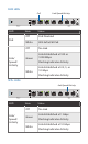
LEDs System System LED State Status Flashing White Initializing. Steady White Factory defaults, waiting for adoption. Alternating White/Blue Device is busy; do not touch or unplug it. This usually indicates that a process such as a firmware upgrade is taking place. Steady Blue Successfully adopted by a network and working properly. Flashing Blue This is used to locate a device. When you click Locate in the UniFi Controller software, the System LED will flash blue.
RJ45 LEDs PoE LED State Link/Speed/Activity Status Off PoE Disabled White 802.3af/at/bt PoE Off No Link Green Link Established at 100 or 1000 Mbps Flashing Indicates Activity White Link Established at 2.
Back Panel DC In Power Ground + Port Description DC Input Optional DC input for connecting a stand-alone or redundant DC power source (not included) with minimum power: 40W, 44 to 57VDC. Power Connect the included Power Adapter to the Power port. Ground Ancillary grounding point for enhanced ESD protection.
Hardware Installation The UniFi Switch can be mounted on a horizontal surface, mounted on a vertical surface, or mounted in a rack (rackmount accessory sold separately). WARNING: The US-XG-6POE must not be stacked. Do not place it on top of another switch. Do not place anything on top of the US-XG-6POE. WARNING: FAILURE TO PROVIDE PROPER VENTILATION MAY CAUSE FIRE HAZARD. KEEP AT LEAST 20 MM OF CLEARANCE NEXT TO THE VENTILATION HOLES FOR ADEQUATE AIRFLOW.
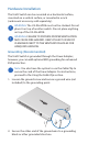
Using the Cable Clip (Optional) 1. Remove the ground screw from the grounding point. 2. Insert the cord of the Power Adapter into the Cable Clip.
3. Connect the Power Adapter to the Power port. 4. Use the ground screw to attach the ground wire (not included) and Cable Clip to the grounding point. 5. Secure the other end of the ground wire to a grounding block or other grounded structure.
Connecting Power Use the included Power Adapter to power the UniFi Switch. You can also use the DC Input option as stand-alone power or a hot backup. Using the Power Adapter 1. If you haven’t already connected the Power Adapter, then connect it to the Power port. 2. Connect the Power Cord to the Power Adapter. Then connect the other end of the Power Cord to a power outlet.
Using the DC Input (Optional) For stand-alone power or redundant backup, connect a DC power source to the UniFi Switch. Note: Only one power source can be used at any one time. With both power sources connected, the input with the highest voltage will be used; the other power source defaults to backup. 1. Connect the 3-pin terminal block connector of a DC/DC cable (not included) to the DC Input. 2. Wire a DC/DC cable (not included) to the DC Input.
Connecting Ethernet 1. Connect an Ethernet cable from your DHCP server or LAN to any port 1 to 4. 2. Connect your other network devices to the remaining RJ45 ports.
Connecting SFP+ To use an SFP+ port: 1. Remove the protective plug covering the SFP+ port. 2. Plug a compatible fiber module into the SFP+ port. D D M K 0 m 2 n CS 0 1 /M 3 1 S xR s /m pb n M 0 0 5 0 5 0 1 1 xT M 3. Connect the fiber optic cable to the fiber module. Then connect the other end of the cable to another fiber device. For information about compatible fiber SFP modules, visit: community.ubnt.
Software Installation Download and install the latest version of the UniFi Controller software at www.ubnt.com/download/unifi and follow the on‑screen instructions. Note: If you already have UniFi Controller v5.8.x or newer installed, skip to the section, Adopting the UniFi Switch. After you have installed the software and run the UniFi Installation Wizard, a login screen will appear for the UniFi Controller management interface. Enter the admin name and password that you created and click Sign In.
Adopting the UniFi Switch 1. From the UniFi Controller dashboard, click Devices in the left menu bar. 2. On the Devices screen, locate the UniFi Switch in the list of devices under the Model column. To adopt the UniFi Switch, click Adopt. 3. The System LED on the UniFi Switch will turn blue to confirm that it has been successfully adopted.
Specifications US-XG-6POE Dimensions 165 x 268.1 x 31.8 mm (6.50 x 10.56 x 1.25") Weight Interfaces Networking Management Power Method Power Supply 1.3 kg (2.87 lb) (4) 100 Mbps or 1/2.5/5/10G RJ45 Ports (2) 1/10G SFP+ Ethernet Ports Ethernet In-Band (1) RJ45 Serial Port Out-of-Band (1) USB Type C Port Out-of-Band 54VDC, 3.88A Power Adapter (Included) or DC Input with Terminal Block External AC/DC Adapter (Included) or DC Power Source Supported Voltage Range 44 to 57VDC Max.
Safety Notices 1. Read, follow, and keep these instructions. 2. Heed all warnings. 3. Only use attachments/accessories specified by the manufacturer. WARNING: Failure to provide proper ventilation may cause fire hazard. Keep at least 20 mm of clearance next to the ventilation holes for adequate airflow. WARNING: To reduce the risk of fire or electric shock, do not expose this product to rain or moisture. WARNING: Do not use this product in location that can be submerged by water.
Limited Warranty www.ubnt.com/support/warranty/ The limited warranty requires the use of arbitration to resolve disputes on an individual basis, and, where applicable, specify arbitration instead of jury trials or class actions. Compliance FCC Changes or modifications not expressly approved by the party responsible for compliance could void the user’s authority to operate the equipment. This device complies with Part 15 of the FCC Rules. Operation is subject to the following two conditions: 1.
CE Marking CE marking on this product represents the product is in compliance with all directives that are applicable to it. RoHS/WEEE Compliance Statement English European Directive 2012/19/EU requires that the equipment bearing this symbol on the product and/or its packaging must not be disposed of with unsorted municipal waste. The symbol indicates that this product should be disposed of separately from regular household waste streams.
Español La Directiva 2012/19/UE exige que los equipos que lleven este símbolo en el propio aparato y/o en su embalaje no deben eliminarse junto con otros residuos urbanos no seleccionados. El símbolo indica que el producto en cuestión debe separarse de los residuos domésticos convencionales con vistas a su eliminación.
Declaration of Conformity български [Bulgarian] С настоящото UBIQUITI NETWORKS декларира, че това устройство US-XG-6POE е в съответствие със съществените изисквания и други приложими разпоредби на Директиви 2014/30/ЕС, 2014/35/ЕС. Цялостният текст на ЕС декларацията за съответствие може да се намери на следния интернет адрес: www.ubnt.
Italiano [Italian] Con la presente, UBIQUITI NETWORKS, dichiara che questo dispositivo US-XG-6POE, è conforme ai requisiti essenziali ed alle altre disposizioni pertinenti delle direttive 2014/30/UE, 2014/35/UE. Il testo completo della dichiarazione di conformità UE è disponibile al seguente indirizzo Internet: www.ubnt.
Online Resources Support help.ubnt.com Community community.ubnt.com Downloads downloads.ubnt.com Ubiquiti Networks, Inc. 685 Third Avenue, 27th Floor New York, NY 10017 USA www.ubnt.com ©2018-2019 Ubiquiti Networks, Inc. All rights reserved. Ubiquiti, Ubiquiti Networks, the Ubiquiti U logo, the Ubiquiti beam logo, TOUGHCable, and UniFi are trademarks or registered trademarks of Ubiquiti Networks, Inc. in the United States and in other countries. Apple and the Apple logo are trademarks of Apple Inc.