Ultra-wideband Location System Modular Ubitag V2.0 User’s Manual Written By Andy Ward Ubisense Limited St Andrew’s House St Andrew’s Road Chesterton Cambridge CB4 1DL ENGLAND Tel: Fax: +44 (0)1223 535 170 +44 (0)1223 535 167 Email: WWW: support@ubisense.net http://www.ubisense.
Table of Contents Introduction ...................................................................................................................................... 1 Regulatory Information for the United States of America................................................................ 1 Regulatory Information for Europe .................................................................................................. 2 Regulatory Information for Canada .....................................................
1 Introduction The Modular Ubitag V2.0 is a wireless module intended to be integrated into other devices for the real-time location of objects within buildings. It transmits ultra-wideband (UWB) pulses which are picked up by a network of basestations (Ubisensors) placed inside the building, allowing the 3D position of the tag to be found.
2 Regulatory Information for Europe Hereby, Ubisense declares that this Modular Ubitag V2.0 is in compliance with the essential requirements and other relevant provisions of Directive 1999/5/EC. A copy of the Declaration of Conformity for this equipment may be obtained from: Ubisense St. Andrew's House St. Andrews Road Chesterton Cambridge CB4 1DL United Kingdom This UWB transmitter must not be installed at a fixed outdoor location or used in flying models, aircraft and other forms of aviation.
3 Modular Ubitag V2.0 Specifications UWB transmitter section Operates under: FCC Part 15.517 (U.S) and EN302500 (E.U.) Centre frequency: -10dB bandwidth: 7.488 GHz 1.014 GHz Conventional 2.4GHz radio transceiver Operates under: FCC Part 15.249 (U.S) and EN300440 (E.U.) Lowest channel frequency: Highest channel frequency: 2402.5MHz 2480.5MHz General specifications Dimensions (WxHxD): Weight: Power supply: Operating temperature range: 24.5mm x 24.5mm x 9mm 6g 2.3V-5.
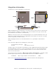
4 Integration information The dimensions of the module PCB are shown below: 24.5mm 20mm Ub ise ns e 24.5mm 20mm 2.1mm 4.5mm 1.6mm 3mm When mounting the tag on another device care must be taken to avoid occlusion of the antennas by tall components, shielding, or mounting screws. There should be an air gap of at least 1mm left around both of the antennas to avoid detuning. While the connector provides some mechanical fixing it is not recommended that this is the only fixing point.
5 Annex A – Additional information pertaining to use of UWB indoors This section lists the regulatory requirements for indoor UWB operation in various territories. Note that this text is presented only for informative purposes, and that all regulatory steps (labeling, instructions to the user, etc.) listed in the main section of this document must be fulfilled by integrators supplying the Ubitag Module V2.0 to users.
6 (1) The UWB transmitter equipment conforming to the present document shall not be: - installed at a fixed outdoor location; - installed or used in flying models, aircraft and other forms of aviation; - installed or used in a road or rail vehicle. (2) To minimize interference to other users of the radio spectrum, in particular outdoor radio stations, the equipment shall transmit only when it is sending information to a receiver or attempting to acquire or maintain association.