
User's Manual

4
Ubisense – Ultra-Wideband Location System – Modular Ubitag V2.0
Integration information
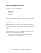
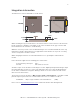
The dimensions of the module PCB are shown below:
When mounting the tag on another device care must be taken to avoid occlusion of the antennas
by tall components, shielding, or mounting screws. There should be an air gap of at least 1mm
left around both of the antennas to avoid detuning.
While the connector provides some mechanical fixing it is not recommended that this is the only
fixing point. A double-sided pad has been supplied that can be fitted to the top of the screening
can to securely fix the module to a PCB.
When designing the PCB it is recommended that there is no ground plane underneath the
module.
Power should be supplied on the following pins of the header:
2.3V-5.25V DC power input: Pin 3
Ground: Pins 5,6,9,10,14,18,19
A number of pins on the module’s header may be used for digital input/output and analogue input.
Note that application-specific use of these pins will require Ubisense to write modified firmware
for the device, and therefore integrators wishing to make use of these features should contact
Ubisense in the first instance.
The header used on the module is a Major League TSHS-5 10-D-04-A-F-LF, a standard 1.27mm
pitch through-hole pin header. The recommended connector to use with the module is:
Connector: Major League LSSHS-5 10-D-06-F-TB-P-LF (SMD)
Please refer to http://www.mlelectronics.com for further information and ordering details.
4.5mm
3mm
2.1mm
1.6mm
4.5mm
3mm
2.1mm
1.6mm
24.5mm
24.5mm
24.5mm
24.5mm
20mm
20mm
U
b
i
s
e
n
s
e
20mm
20mm
U
b
i
s
e
n
s
e