
User's Manual
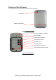
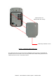

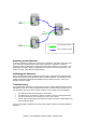

Table Of Contents

Ubisense – Ultra-wideband Location System – Ubisensor30v1
Installation and Operation Instructions
Mounting options
Ubisensors have three mounting holes in the back of the case, to which external clamps and
brackets can be attached. The two outer holes are M4 size, the middle hole is M6 size (and
can be used in conjunction with a standard photographic camera mount).
Powering the Ubisensors
Ubisensors must be powered using Power over Ethernet (PoE). This is normally done by
connecting the sensors to the network using a PoE switch. However, it is also possible to use
mid-span injectors if desired.
Setting up a sensor group
Ubisense will have supplied you with an updated location system database containing
configuration information for the equipment you have received. At this point, it’s worth
checking that the MAC (Media Access Control) addresses of the Ubisensors you have
received match the information in the database, using the Ubisense location system
configuration tools. See the software manual for details on how to examine the contents of the
configuration database – the MAC address for each Ubisensor is printed on a label affixed to
the rear of the unit (see “Features of the Ubisensor”).
Once you are sure you have the correct equipment to hand, the sensor cells for the system
can be set up. In the Ubisense location system, a large area of space is covered by a number
of sensor groups, each of which (individually) covers a smaller area.
Each sensor group has a number of units which are synchronized together using a timing
signal conveyed between the units by timing cables. The cables interconnecting the units are
unshielded Category 5e cable (or better).
Each sensor group has one sensor which is configured as a Timing Source. The remaining
sensors are configured not to be Timing Sources.
A timing cable from the Timing Source to other sensors can be plugged into any free timing
socket on the Timing Source, but must be plugged into the bottom left-hand timing socket
(Marked “5”) on the other sensors.
All sensors are connected to the standard network using a Category 5 unshielded cable (or
better). Power is supplied over the network cabling using Power over Ethernet (PoE)
techniques, so the sensors must be connected to the network via a PoE switch (or
alternatively to a non-PoE switch via mid-span PoE injectors).
The final wiring interconnection diagram for a three-member sensor cell would be as follows: