
System Description Chapter 2


500-Watt VHF Low Band Transmitter Chapter 2, System Description
325A, Rev. 0 2-3
2.2.1 VHF Exciter Tray
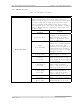
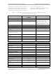
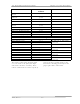
Table 2-2. VHF Exciter Tray Meters
METER FUNCTION
This meter reads power in terms of a percentage of the
calibrated output power level on the upper scale. The
voltage level or frequency level is read on one of the bottom
two scales. A full-scale reading on the top scale is 120%.
100% is equivalent to the full-rated 500 watts peak of
sync visual. The meter also reads % Aural Power, % Exciter
Power, % Reflected Power, audio levels, video levels, and
the ALC reading.
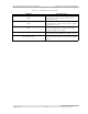
With Switch S3 in
Position
Display
Switch S3, Meter
Selects the desired ALC voltage
reading, % Exciter Power, %
Reflected Power, % Visual
Power, % Aural Power, video
level, or audio level.
Audio
(0 to 100 kHz)
Reads the audio level, ±25 kHz
balanced or ±75 kH composite,
on the 0 to 10 scale. Will
indicate baseband audio, if it is
connected to the transmitter,
even with the video + 4.5-MHz
SCA input selected.
ALC
(0 to 10 volts)
Reads the ALC voltage level, .8
VDC, on the 0 to 10 scale.
% Exciter
(0 to 120)
Reads the % Exciter Output
Power Level needed to attain
100% output of the transmitter
on the top scale.
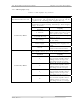
% Aural Power
(0 to 120)
Reads the % Aural Output
Power of the transmitter,
100% = 100 watts at 10 dB
A/V ratio, on the top scale.
% Visual Power
(0 to 120)
Reads the % Visual Output
Power of the transmitter,
100% = 500 watts peak of
sync, on the top scale.
% Reflected
(0 to 120)
Reads the % Reflected Output
Power, <5%, on the top scale.
Meter (A4-A18)
Video
(0 to 1 volt)
Reads the video level, at white,
on the bottom 0 to 10 scale.