
System Description Chapter 2


500-Watt VHF Low Band Transmitter Chapter 2, System Description
325A, Rev. 0 2-8
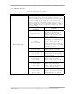
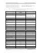
The remote connections listed in Table 2-
10 are made to the (A12) A/V input and
remote interface assembly. The remote
connections are made to jacks J9 and J10
on the assembly. Refer to the
interconnect drawing (1076203) for the
proper pin remote connections.
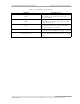
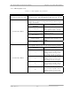
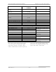
Table 2-10. VHF Exciter Remote Interface Connections with the A/V Input
and Remote Interface Assembly
FUNCTION REMOTE JACK/PIN
NUMBER
INTERFACE TYPE
Transmitter Enable Interlock J9-21
Transmitter Enable Interlock
Rtn.
J9-22
J9-21 and J9-22 must be
jumpered together for
normal operation. The
(1176-1038) jumper jack
should be used.
Remote Control Commands
Transmitter Standby
(Disable)
J9-9 Contact closure
Transmitter
Standby/Operate Rtn.
J9-10
Transmitter Operate
(Enable)
J9-11
Contact closure
Transmitter Manual J9-15 Contact closure
Transmitter Auto/Manual
Rtn.
J9-16
Transmitter Auto J9-17 Contact closure
Power Level Raise (Optional) J9-27 Contact closure
Pwr Lvl Raise/Lower Rtn
(Optional)
J9-28
Power Level Lower
(Optional)
J9-29
Contact closure
Modulator Select (Optional) J9-31 Contact closure
Modulator Select Rtn
(Optional)
J9-32
Remote Status Indications
Transmitter Operate
(Enable) Ind.
J9-12
50 mA max current sink
Operate/Standby Ind.
Return
J9-13
Transmitter Standby
(Disable) Ind.
J9-14
50 mA max current sink
Transmitter Auto Indicator J9-18 50 mA max current sink