INSTRUCTION MANUAL 335B 3300 WATT VHF LOW BAND TRANSMITTER AXCERA, LLC 103 FREEDOM DRIVE P.O. BOX 525 LAWRENCE, PA 15055-0525 USA (724) 873-8100 • FAX (724) 873-8105 www.axcera.com • info@axcera.
3300-Watt VHF Low Band Transmitter Table of Contents TABLE OF CONTENTS CHAPTER 1 INTRODUCTION SECTION 1.1 1.2 1.3 1.4 1.5 1.6 PAGE Manual Overview ...................................................................................1-1 Assembly Designation Procedure.............................................................1-1 Safety ..................................................................................................1-1 Contact Information...................................................
300-Watt VHF Low Band Transmitter Table of Contents TABLE OF CONTENTS (continued) SECTION PAGE 4.4 Harmonic Filter, Bandpass Filter and Coupler Assembly ........................... 4-31 CHAPTER 5 DETAILED ALIGNMENT PROCEDURES 5.1 5.2 5.3 5.4 5.5 5.6 VHF Low-Band Exciter Tray with Baseband Video and Audio Inputs.............5-1 VHF Exciter Tray with 4.5-MHz Composite Input Kit ..................................5-2 VHF Exciter Tray with Either Baseband or 4.5-MHz Composite Input ...........
3300-Watt VHF Low Band Transmitter Table of Contents LIST OF FIGURES FIGURE PAGE 3-1 3-2 1 kW Minimum Ventilation Configuration...........................................3-4 Chassis Trak Cabinet Slides .............................................................3-5 5-1 Waveform.................................................................................... 5-11 335B, Rev.
3300-Watt VHF Low Band Transmitter Table of Contents LIST OF TABLES TABLE PAGE 2-1 2-2 2-3 2-4 2-5 2-6 2-7 2-8 2-9 2-10 335B Trays and Assemblies .............................................................2-1 VHF Exciter Tray Meters ..................................................................2-5 VHF Exciter Tray Switches ...............................................................2-6 VHF Exciter Tray Fault Indicators .....................................................
3300-Watt VHF Low Band Transmitter Chapter 1, Introduction Chapter 1 Introduction This manual explains the installation, setup, alignment, and maintenance procedures for the 335B 3300-watt solid state VHF Low Band transmitter. It is important that you read all of the instructions, especially the safety information in this chapter, before you begin to install or operate the unit. provided in the appendices. These supporting documents are arranged in increasing numerical order in the appendices.
3300-Watt VHF Low Band Transmitter Chapter 1, Introduction Follow Instructions – All of the operating and use instructions for the transmitter should be followed. 2. 3. 4. Cleaning – Unplug or otherwise disconnect all power from the equipment before cleaning. Do not use liquid or aerosol cleaners as damage to silk screens may occur. Use a damp cloth for cleaning. 5. Ventilation – Openings in the cabinets and tray front panels are provided for ventilation.
3300-Watt VHF Low Band Transmitter Chapter 1, Introduction When shipping an item to Axcera, please include the MRA# on the packing list and on the shipping container. The packing list should also include contact information and a brief description of why the unit is being returned.
3300-Watt VHF Low Band Transmitter Chapter 2, System Description, Maintenance & Remote Control Connections Chapter 2 System Description, Maintenance & Remote Control Connections The 335B is a complete 3300-watt VHF Low Band solid state internally diplexed television transmitter that operates at a nominal visual output power of 3300 watts peak sync and an average aural output power of 330 watts, at an A/V ratio of 10 dB, 10% sound, or 165 watts at 13 dB, 5% sound. 2.
3300-Watt VHF Low Band Transmitter Chapter 2, System Description, Maintenance & Remote Control Connections modulated 4.5 MHz IF, from the aural IF synthesizer board, is mixed with the 45.75 MHz CW to produce a modulated 41.25 MHz aural IF output. The video modulated 45.75 MHz is then diplexed with the audio modulated 41.25 MHz to produce the combined Visual IF + Aural IF output of the board that connects to the ALC board.
3300-Watt VHF Low Band Transmitter Chapter 2, System Description, Maintenance & Remote Control Connections Channel Oscillator Board VHF Low Band Amplifier Tray NOTE: If the precise frequency kit is present in your transmitter, the VCXO Channel Oscillator Board (1145-1204) will be used. The outputs of the splitter feed the three (A6, A7 and A11) VHF amplifier trays (1304363). Each tray amplifies the RF signals to approximately 750 watts peak of sync visual + aural.
3300-Watt VHF Low Band Transmitter Chapter 2, System Description, Maintenance & Remote Control Connections 2.2 Control and Status of Transmitter NOTE: If the remote interface panel is not present in your transmitter the dummy jumper plug must be present on J11, with a jumper between pins 23 and 24, located on the back of the VHF exciter tray. The jumper provides the interlock needed for the transmitter to operate.
3300-Watt VHF Low Band Transmitter Chapter 2, System Description, Maintenance & Remote Control Connections 2.2.1 VHF Exciter Tray (A4) Table 2-2. VHF Exciter Tray Meters METER Meter (A4-A18) 335B, Rev. 0 FUNCTION This meter reads power in terms of a percentage of the calibrated output power level on the upper scale. The voltage level or frequency level is read on one of the bottom two scales. A fullscale reading on the top scale is 120%.
3300-Watt VHF Low Band Transmitter Chapter 2, System Description, Maintenance & Remote Control Connections Table 2-3. VHF Exciter Tray Switches SWITCH S1 Transmitter Operate/Standby S2 Mode Select Auto/Manual R1 Power Adjust FUNCTION The momentary switch S1 applies a ground to K1, a latching relay on the transmitter control board. K1 will switch either to Operate or to Standby depending on which direction S1 is pushed.
3300-Watt VHF Low Band Transmitter Chapter 2, System Description, Maintenance & Remote Control Connections 2.2.2 VHF Amplifier Tray (A6, A7 & A11) Table 2-6. VHF Amplifier Tray Switches SWITCH CB1 On/Off Circuit Breaker S1 Switch, Meter S2 Switch, Meter 335B, Rev. 0 FUNCTION Switches 220 VAC through a 15-amp circuit breaker-type protection device. The switch lights if AC is present. The AC is applied to the switching power supply in the tray.
3300-Watt VHF Low Band Transmitter Chapter 2, System Description, Maintenance & Remote Control Connections Table 2-7. VHF Amplifier Tray Fault Indicators INDICATOR DS1 Overdrive DS2 Enable DS3 Module Status DS4 VSWR Cutback DS5 Overtemperature DESCRIPTION Indicates that the level of drive is too high. The protection circuit will limit the drive level to the set threshold. The fault is generated on the overdrive protection board.
3300-Watt VHF Low Band Transmitter Chapter 2, System Description, Maintenance & Remote Control Connections this data be retained in a rugged folder or envelope. A sample format for a log sheet is provided in Appendix B. Photocopies of the log sheet should be made to allow you to make continued data entries. system, the baseband video and audio inputs connect directly to the rear of the VHF exciter. NOTE: If your transmitter does not contain the 4.
3300-Watt VHF Low Band Transmitter Chapter 2, System Description, Maintenance & Remote Control Connections Table 2-10. 335B Remote Interface Connections to (A12) the A/V Input and Remote Interface Assembly REMOTE JACK/PIN NUMBER FUNCTION Transmitter Enable Interlock J9-21 Transmitter Enable Interlock Rtn. J9-22 INTERFACE TYPE J9-21 and J9-22 must be connected together for normal operation. The (1176-1038) jumper jack or an external interlock can be used.
3300-Watt VHF Low Band Transmitter FUNCTION Chapter 2, System Description, Maintenance & Remote Control Connections REMOTE JACK/PIN NUMBER Remote Metering INTERFACE TYPE Visual Output Power Visual Output Power Rtn J9-1 J9-2 1V full scale at 1kΩ source resistance Aural Output Power Aural Output Power Rtn J9-3 J9-4 1V full scale at 1kΩ source resistance Reflected Power Reflected Power Rtn J9-5 J9-6 1V full scale at 1kΩ source resistance Exciter Output Power Exciter Output Power Rtn J9-7 J9-8 1
3300-Watt VHF Low Band Transmitter Chapter 3, Installation and Setup Procedures Chapter 3 Installation and Setup Procedures There are special considerations that need to be taken into account before the 335B can be installed. For example, if the installation is completed during cool weather, a heat-related problem may not surface for many months, suddenly appearing during the heat of summer. This section provides planning information for the installation and set up of the transmitter.
3300-Watt VHF Low Band Transmitter Chapter 3, Installation and Setup Procedures Now that the amount of heat that must be removed is known, the next step is to determine how to accomplish this. The options are air conditioning, ventilation, or a combination of the two. Air conditioning is always the preferred method and is the only way to create anything close to an ideal environment. transmitter under certain conditions.
3300-Watt VHF Low Band Transmitter 5. 6. 7. 8. Chapter 3, Installation and Setup Procedures The exhaust should be located as high as possible. Some ducting is usually required to insure the complete flushing of heated air with no stagnant areas. The area of the filter, located in the ducting, must be large enough to insure a maximum air velocity of 300 feet per minute through the filter. This is not a conservative number but a never-exceed number.
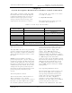
3300-Watt VHF Low Band Transmitter Chapter 3, Installation and Setup Procedures Figure 3-1. 1 kW Minimum Ventilation Configuration 3.2 Unpacking the Cabinet and Trays Remove the cabinet and the trays from the crates and boxes. Remove the straps that hold the cabinet to the shipping skid and slide the cabinet from the skid. Remove the plastic wrap and foam protection from around the cabinet.
3300-Watt VHF Low Band Transmitter Chapter 3, Installation and Setup Procedures Figure 3-2. Chassis Trak Cabinet Slides Open the rear door and inspect the interior of the cabinet for packing materials and carefully remove any that are found. Slowly slide each tray in and out to verify that they do not rub against each other and have no restrictions to free movement. It may be necessary to adjust the position of the trays to keep them from rubbing.
3300-Watt VHF Low Band Transmitter Chapter 3, Installation and Setup Procedures This completes the unpacking and installation of the 335B 3300-watt VHF television transmitter. Refer to the setup and operation procedures that follow before applying power to the transmitter. If the (A12) A/V input and remote interface assembly is not present in the system, connections are made directly to the rear of the VHF exciter tray.
3300-Watt VHF Low Band Transmitter Chapter 3, Installation and Setup Procedures panels of the VHF amplifier trays, in the power supply position. not be the same. Refer to the Test Data Sheet for the transmitter to compare the final readings from the factory with the readings on each of the trays after the setup.
3300-Watt VHF Low Band Transmitter Chapter 4, Circuit Descriptions Chapter 4 Circuit Descriptions 4.1 (A4) Low Band VHF Exciter (1070820 or 1304463 w/P.F.; Appendix C) is applied to the board. The outputs of U1B and U1C are applied to the differential amplifier U1A that eliminates any common mode signals (hum) on its input leads. A pre-emphasis of 75 µs is provided by R11, C11, and R10 and can be eliminated, if not needed, by removing the jumper W5 on J5.
3300-Watt VHF Low Band Transmitter Chapter 4, Circuit Descriptions mode signals (hum) that may occur on its input leads. The composite audio input signal is applied to the amplifier U2B whose gain is controlled by the composite audio gain pot R17. The composite audio signal is then connected to the summing point at U2D pin 13. U11B. The output of U11B is connected to the 4.5-MHz output jacks at J7 and J8. 4.1.1.5 Phase Lock Loop (PLL) Circuit A sample of the signal from the 4.
3300-Watt VHF Low Band Transmitter Chapter 4, Circuit Descriptions -12 VDC is connected to J1-5 and filtered by L1, C1, and C2 before it is connected to the rest of the board. Two connections of the +12 VDC are to U8 and U9, which are 5-volt regulator ICs that provide the voltage to the U10 and U5 ICs. Test point TP1 is provided to monitor the level of the input.
3300-Watt VHF Low Band Transmitter Chapter 4, Circuit Descriptions video that is split off from the main video path at the emitter of Q3. The video sample is buffered by U3A and connected to U4A. The level at which the tip of sync is clamped, approximately -1.04 VDC, as measured at TP2, is set by the voltagedivider network connected to U4A. If the video level changes, the sample applied to U4A changes.
3300-Watt VHF Low Band Transmitter Chapter 4, Circuit Descriptions 1, the L input of mixer Z1. The adjustable capacitor C78 and resistor R53 are set up to add a small amount of incidental carrier phase modulation (ICPM) correction to the output of the mixer stage to compensate for any nonlinearities generated by the mixer. 45.75-MHz IF carrier oven oscillator board or the IF VCXO board, in a precise frequency system. The modulated baseband 4.
3300-Watt VHF Low Band Transmitter Chapter 4, Circuit Descriptions The Mixer Z2 heterodynes the auralmodulated, 4.5-MHz signal with the 45.75-MHz CW signal to produce the modulated 41.25-MHz aural IF signal output. combines the NICAM signal with the 45.75-MHz visual IF + 41.25-MHz aural IF signal. The output of the mixer at pin 4, the R output, is fed to a bandpass filter that is tuned to pass only the modulated 41.25MHz aural IF signal. The bandpass filtered signal is fed to jack J16, the 41.
00-Watt VHF Low Band Transmitter Chapter 4, Circuit Descriptions is attained. The delay-equalized video signal output of the board is at J1-4. A sample of the delayed video signal is provided at J2 on the board and can be used for testing purposes. pF, prevents the oscillator from being loaded down by Q2. Q2 is operated as a common-emitter amplifier stage whose bias is provided through R8 from the +12 VDC line.
3300-Watt VHF Low Band Transmitter Chapter 4, Circuit Descriptions The stages U1, U2, U3, Q5, and Q6 are powered by +5.1 VDC, which is obtained from the +12 VDC line voltage using the voltage-dropping resistor R16 and the zener diode VR2. 10 pF, prevents the oscillator from being loaded down by Q2. Q2 is operated as a Common Emitter Amplifier stage whose bias is provided through R8 from the +12 VDC line.
3300-Watt VHF Low Band Transmitter Chapter 4, Circuit Descriptions voltage dropping resistor R16 and Zener Diode VR2. If a receiver tray is part of your system, then the relays need to be controlled by the Modulator Select command that is connected to J30 on the board, so that either the receiver IF or the modulator IF can be used by the board. The position of the Modulator select enable/disable jumper W11 on J29 provides for the Modulator Select command at J30 to control the operation of the relays.
3300-Watt VHF Low Band Transmitter 4.1.5.5 Main IF Signal Path (Part 1 of 3) The selected visual + aural IF input (0 dBm) signal is split at L1 and L2, with one half of the signal flowing through L1 and entering a bandpass filter that consists of L3, L4, C4, L5, and L6. This bandpass filter can be tuned with C4 and is substantially broader than the IF signal bandwidth.
3300-Watt VHF Low Band Transmitter Chapter 4, Circuit Descriptions comparator circuit made up of U9C and U9D. The reference voltage for the comparators is determined by a voltage divider network consisting of R129, R64, R65, R66, and R130, off the -12 VDC line. When the input signal level falls below this reference threshold, which acts as a loss of sync detector circuit, the outputs of U9C and U9D move towards the -12 VDC rail.
3300-Watt VHF Low Band Transmitter attenuator (minimum signal output). By controlling the value of the voltage applied to the pin diodes, the IF signal level is maintained at the set level. 4.1.5.8 Main IF Signal Path (Part 2 of 3) When the IF signal passes out of the pindiode attenuator through C11, it is applied to the modular amplifier U1. This device includes within it the biasing and impedance matching circuits that makes it operate as a wide-band IF amplifier.
3300-Watt VHF Low Band Transmitter sample of the corrected IF is provided at TP2. The IF output is normally connected to an external IF phase corrector board. Chapter 4, Circuit Descriptions frequency-response correction takes place. 4.1.5.11 ALC Circuit 4.1.5.10 Main IF Signal Path (Part 3 of 3) After the IF signal passes through the external IF phase corrector board, it returns to the ALC board at IF input jack J7 (0 dBm).
3300-Watt VHF Low Band Transmitter This ALC voltage, and the DC level corresponding to the IF level after signal correction, are fed to U10A pin 2, whose output at pin 1 connects to the ALC pindiode attenuator circuit, CR1-CR3. If there is a loss of gain somewhere in an IF circuit, the output power of the transmitter will drop and the ALC circuit will sense this drop at U10A that will automatically lower the loss of the pindiode attenuator circuit that increases the IF level through the attenuator circuit.
3300-Watt VHF Low Band Transmitter than just pulling the ALC reference down. Two different mechanisms are employed. One is a very fast-acting circuit to increase the attenuation of the pin-diode attenuator, CR3, CR1, and CR2, and the second is the reference voltage being pulled away from the ALC amplifier device. An external Mute is a pull-down applied to J19 pin 6, to provide a current path from the +12 VDC line through R78 and R139, the LED DS4 (Mute indicator), and the LED section of opto-isolator U11.
3300-Watt VHF Low Band Transmitter the signal. This attenuation is adjusted by adding R7, a variable resistor, in parallel with the L-pad. R7 is only in parallel when the signal reaches a level large enough to bias on CR1 and CR2 that allows current to flow through R7. When R7 is put in parallel with the L-pad, the attenuation through the L-pad is lowered, causing black stretch. The threshold for the first corrector stage is set by controlling where CR1 and CR2 turn on.
3300-Watt VHF Low Band Transmitter The amount of stretch is determined by the adjustment of R35. The signal is next applied to the amplifier U5 to compensate for the loss in level through the L-pad. The breakpoint, or cut-in point, for the corrector stage is set by controlling where CR8 and CR9 turn on. This is achieved by adjusting the cut-in resistor R31 to form a voltage divider from +6.8 VDC to ground. The voltage at the wiper arm of R31 is buffered by the unity-gain amplifier U8B.
3300-Watt VHF Low Band Transmitter at J2. The typical LO signal output level is +5 dBm. The voltage measured at TP2 is typically +0.6 VDC. The +12 VDC for the board enters through jack J3-3 and is filtered by L3, C2 and C7 before being distributed to the rest of the board. 4.1.7.
3300-Watt VHF Low Band Transmitter or auto gain by its position on the jack. Between 1 and 2 is manual gain, which uses pot R9 to set the output level. Between pins 2 and 3 is auto gain, which uses an external control voltage input at jack J4 as the level control. NOTE: The 335B transmitter operates in Manual only. The level set RF is pre-amplified by U1 and connected to Q1, the output amplifier for the board.
3300-Watt VHF Low Band Transmitter standby indicator, if present, and J18-1. The low from U4B-13 also connects to Q10, which is biased on, and connects a high to Q6, Q7, Q8, and Q9, which are biased on and apply -12 VDC enables to J8-2, J8-3, J8-4, and J8-5 that connect to the VHF amplifier trays. The high applied to Q2 is also connected to Q5, which is biased on, and applies a low enable to J1-3, which connects to the remote operate indicator, if present, turning it on.
3300-Watt VHF Low Band Transmitter 4.1.8.3 The Automatic Turning On and Off of the Transmitter Using the Presence of Video. The transmitter control board also allows the transmitter to be turned on and off by the presence of video at the transmitter when the transmitter is in Auto. When a video fault occurs due to the loss of video, J7-5 goes low. The low is applied through the jumper W1, on J10, to Q16, which is biased off, and to the red Video Loss Fault LED DS9, on the front panel, which will light.
3300-Watt VHF Low Band Transmitter high at U5C pins 8 and 9, causes its output at pin 10 to go low. This low is connected to U5D pin 12. If the transmitter is in Auto, pin 13 of U5D is also low. The lows on pins 12 and 13 cause the output of U5D to go high and forward bias Q19. The drain of Q19 goes low and energizes the coil connected to pins 1 and 6 in relay K1, causing it to switch to Standby. When the video returns, the video loss fault is removed from the video fault input at J7-5.
3300-Watt VHF Low Band Transmitter J8-37 for the connection to a remote VSWR cutback indicator. 4.1.8.8 Receiver ALC Fault If a receiver tray is part of the system, a sample of the ALC voltage from this tray is connected to J8-11 on the transmitter control board. If the receiver is operating normally, the ALC level that is applied to U3C pin 9, remains below the trip level set by R35; as a result, the output at pin 13 stays high. The high is applied to the red ALC Fault LED DS8, which is off.
3300-Watt VHF Low Band Transmitter • • • • % Aural power = 100% % Exciter = The level on the meter needed to attain 100% output power from the transmitter ALC = .8 VDC Audio = ±25 kHz with a balanced audio input or ±75 kHz with a composite audio input Refer to the test data sheet for the transmitter for the actual reading: Chapter 4, Circuit Descriptions for monitoring on the front panel meter.
3300-Watt VHF Low Band Transmitter 4.1.9.2 Visual Level Circuit The other detected visual + aural level output from U6B is connected to U1C and, if there is no scrambling, connects directly to intercarrier notch L3, which is adjusted to filter out the aural and the 4.5-MHz intercarrier frequencies, leaving only a visual + sync output. The visual + sync output is fed to a peak detector circuit consisting of CR5 and U2A.
3300-Watt VHF Low Band Transmitter (1145-1201) that generates a stable frequency reference signal of approximately 100 MHz. The channel oscillator assembly is an enclosure that provides temperature stability for the crystal oscillator. An SMA output at jack J1 and an RF sample at BNC connector jack J2 are also part of the assembly. Adjustments can be made through access holes in the top cover of the assembly.
3300-Watt VHF Low Band Transmitter determines the length of time between the sending of the identification code. R14 is adjusted to set this time interval. R14, fully CW, is the longest interval between identification calls, approximately eight minutes. R14, fully CCW, is the shortest interval between the sending of the code (approximately 10 seconds). U6B is an amplifier connected to the output of U5, which turns the LED DS1 on and off at the rate set by R2.
3300-Watt VHF Low Band Transmitter Chapter 4, Circuit Descriptions assembly) MAJOR ASSEMBLY DESIGNATOR A3-A2 A3-A3 A4-A1, A4-A2 and A4-A3 A5-A1 A13 A8 A10 BOARD/ASSEMBLY NAME Overdrive protection board (mounted in [A3] an RF enclosure assembly) 3-way splitter board (mounted in [A3] an RF enclosure assembly) Three low band VHF amplifier pallets (mounted in [A4] an RF enclosure assembly) 3-way combiner board (mounted on [A5] the combiner heatsink assembly) AGC control board Current metering board +30 VDC s
3300-Watt VHF Low Band Transmitter J1 on the low band VHF amplifier board (1198-1605) that amplifies the signal approximately 22 dB. The RF output of the low band VHF amplifier board at J2 (+41.5 dBm) connects to J4 of (A3-A2) the overdrive protection board (1198-1601). The RF signal is through connected directly to J5, the RF output jack of the board. A sample of the RF on the board is applied to a diode-detector circuit that consists of CR1 and U1A.
3300-Watt VHF Low Band Transmitter shifter board, the (A2-A2) filter/amplifier board and the (A3-A2) overdrive protection board. The fuses F1, F2 and F3 are 20-amp fuses. F4 is a 5-amp fuse, F6 is a 2-amp fuse, and F7 is a 1-amp fuse. F5 is not used in this configuration.
3300-Watt VHF Low Band Transmitter Front Panel Metering The front panel meter (A9) uses the front panel Selector switch S1 to monitor the AGC Voltage, % Forward Power, % Reflected Power, the power supply voltage, and the current. The meter in the AGC position will read between 1 and 2 volts. The power supply voltage reading is calibrated using R86 on the AGC control board. The % Output Power is calibrated using R44 and the % Reflected Power is calibrated using R53 on the AGC control board.
3300-Watt VHF Low Band Transmitter connector J2 is then fed to the antenna for your system. 335B, Rev. 0 Chapter 4, Circuit Descriptions This completes the description of the 335B VHF Low Band Transmitter.
3300-Watt VHF Low Band Transmitter Chapter 5, Detailed Alignment Procedures Chapter 5 Detailed Alignment Procedures The 335B transmitter was aligned at the factory and should not require additional alignments to achieve normal operation. interface panel. Jacks J1 and J2 on the VHF exciter tray are loop-through connected and the unused jack J2 can be used as a video source for another transmitter by removing jumper W4 on jack J3 on (A5) the sync tip clamp modulator board (1265-1302).
3300-Watt VHF Low Band Transmitter Chapter 5, Detailed Alignment Procedures 5.2 (A4) VHF low-Band Exciter Tray with the 4.5-MHz Composite Input Kit (NOTE: If your transmitter does not contain the 4.5MHz composite input kit, skip this section.) changed with the adjustment of the envelope delay. 5.3 (A4) VHF Exciter Tray with either Baseband or the 4.5-MHz Composite Input With the 4.
3300-Watt VHF Low Band Transmitter • DS4 (Mute) – Indicates that a visual Mute command is present. (NOTE: not used in this configuration) • DS5 (Modulator Enable) – Indicates that the modulator IF output has been selected (NOTE: this is only used if a receiver tray is present in the system. DS5 is always on with no receiver present.) Chapter 5, Detailed Alignment Procedures clockwise (CCW). R68 is the range adjustment and should be set in the middle of the range.
3300-Watt VHF Low Band Transmitter Chapter 5, Detailed Alignment Procedures threshold point. Refer to the assembly drawing for the ALC board (1265-5305), to find the adjustments for the first through third linearity corrector stages. Because the stages are cascaded, the order of correction is important. The first stage should cut in near white level, with the cut-in point of the next stage toward black, and with the last stage primarily stretching sync.
3300-Watt VHF Low Band Transmitter Chapter 5, Detailed Alignment Procedures (1142-1601) in Manual. The idling currents for the amplifier boards are adjusted with no RF drive applied. Remember to put S1 back to the Auto AGC position after any adjustments. Auto AGC is the normal position during operation of the transmitter. Connect a dummy load with a rating of at least 750 watts to J2, the RF output jack of the tray being aligned, before beginning the alignment procedure. gain.
3300-Watt VHF Low Band Transmitter Chapter 5, Detailed Alignment Procedures to 110%, sync only, and adjust R12 until the output power begins to drop off. Return the output power level of the transmitter to 100%. in the VHF L.B. amplifier tray, to the Manual position. Turn the transmitter to the Operate position. 2. Connect a sync and black test signal to the video input jack of the remote interface panel. 5.6.
3300-Watt VHF Low Band Transmitter Chapter 5, Detailed Alignment Procedures panel lights. This sets up the VSWR cutback circuitry. Readjust R5 for 100% on the meter to achieve a 750 watts peak of sync output + 75 watts aural power. However, if the system requires less output power per amplifier tray, adjust each tray by the same amount to give the desired total output power. Turn On the AC to the middle amplifier tray and adjust its' output power to 50%.
3300-Watt VHF Low Band Transmitter Chapter 5, Detailed Alignment Procedures Reflected Power. Be careful not to increase Reflected Power on the other Amplifier Trays. The Amplifier Trays should interact in such a way that the phasing of any one amplifier tray will affect the Reflected on the other amplifier trays. With the spectrum analyzer set to the zero span mode, obtain a peak reference on the screen. Reconnect jumper cable W1 to J16 on (A5) the sync tip clamp/modulator board.
3300-Watt VHF Low Band Transmitter Chapter 5, Detailed Alignment Procedures 5.10 (A8) 3-Way Combiner Assembly (1065241; Appendix C) The tray has been factory tuned and should not need any alignments to achieve normal operation. To align the tray for the 4.5-MHz composite input, apply the 4.5-MHz composite input, with the test signals used as needed, to the video input jack (J1 or J2 [loop-through connections]) on the rear of the tray. Select the 4.
3300-Watt VHF Low Band Transmitter and potentiometers (R7, R12, R17, and R22) until the signal attains the FCC group delay curve. The stages are arranged in order of increasing frequency. Adjust R29, as needed, to attain the same level out of the board as into the board. 5.12.3 (Optional) (A24) Composite 4.5-MHz Filter Board (1227-1244; Appendix D) This board is part of the 4.5-MHz input kit and will only function properly with a 4.5-MHz composite input signal and the 4.5-MHz composite input selected.
3300-Watt VHF Low Band Transmitter Chapter 5, Detailed Alignment Procedures jumper W7 on jack J4 to the Clamp-Off, Disable, position. 3. Connect a 5-step staircase video test signal to the input of the transmitter. 4. Monitor TP2 with an oscilloscope. Adjust R12, the video gain pot, for 1 Vpk-pk. 5. Change the video input test signal to a multiburst test pattern. While monitoring TP2, adjust C8 and R32 for a flat-frequency response. Change the input video test signal back to the 5-step staircase. 6.
3300-Watt VHF Low Band Transmitter 10. Move jumper W7 on J4 to the Clamp Enable position. Readjust pot R152, depth of modulation, for the correct depth of modulation. 11. Set the waveform monitor to display ICPM. Preset R53 fully CCW, adjust C78 for the greatest effect at white on the ICPM display, and then adjust R53 for minimum ICPM. 12. Recheck the depth of modulation and, if necessary, adjust R152, depth of modulation. 13.
3300-Watt VHF Low Band Transmitter D. 2. 3. Connect a cable from the 600Ω audio output jack of the demodulator to the input of an audio distortion analyzer. Set the output frequency of the audio oscillator to 400 Hz and the output level to +10 dBm. Chapter 5, Detailed Alignment Procedures 4. Adjust R13, balanced audio gain, on the aural IF synthesizer board for ±25-kHz deviation. 5. Check the distortion on the aural distortion analyzer (THD=< 0.5%). 6.
3300-Watt VHF Low Band Transmitter 2. The combined IF output of the sync tip clamp modulator board is cabled to jack J32 of the ALC board. Remove J32 from the board, and look to see if DS1, Input Fault, is illuminated. Reconnect J32 and make sure that DS1 is extinguished. 3. Jumper W3 on J6 should be in the Manual position. Monitor jack J3 with a spectrum analyzer. 4. With a multiburst video signal present, tune C4 for a flatfrequency response of ±0.5 dB.
3300-Watt VHF Low Band Transmitter 9. of the transmitter. R103 and R106 are used to adjust the depth and width of the correction notch. 3. The linearity correctors are set up during the system alignment procedure. Controls R13, R18, and R23, the magnitude controls, should be set fully CW. Controls R34, R37, and R40 are the linearity cut-in adjustments. NOTE: Do not repeak C6, C18, L2, or L4. This may change the output level. 5.12.
3300-Watt VHF Low Band Transmitter 5.12.13 (A11-A2) VHF Filter/Mixer Board (1153-1101; Appendix D) Typically a +15dBm RF input at J3, a 0dBm combined IF input at J7, and a RF output of 0dBm at J2. To align the board: 1. 2. Monitor J4, the LO output of the board, with a spectrum analyzer and adjust C12 and C18 for maximum output (+14 dBm) at the LO frequency and minimum out-of-band products. Adjust C13 and C17 for the best frequency response for the LO frequency.
APPENDIX A SYSTEM SPECIFICATIONS
APPENDIX B SAMPLE LOG REPORT SHEET AND TYPICAL READINGS
3300-Watt VHF Low Band Transmitter Appendix B, Sample Log Report Sheet VHF Exciter (A4) ALC (0 to 1 V) = ____________V % Aural Power (0 to 120) = __________% % Exciter (0 to 120) = ______________% Video (0 to 1 V) = ________________IRE % Reflected (0 to 120) = ____________% Audio (0 to 100 kHz) = ____________kHz % Visual Power (0 to 120) = _________% VHF Amplifier Trays #1 (A5) #2 (A6) AGC Voltage (0 to 10 V) = ___________V AGC Voltage (0 to 10 V) = ___________V % Reflected Power (0 to 120) = _
3300-Watt VHF Low Band Transmitter Appendix B, Sample Log Report Sheet VHF Amplifier Trays #1 (A7) #2 (A10) AGC Voltage (0 to 10 V) = ___________V AGC Voltage (0 to 10 V) = ___________V % Reflected Power (0 to 120) = _______% % Reflected Power (0 to 120) = _______% % Output Power (0 to 120) = ________% % Output Power (0 to 120) = ________% Power Supply Voltage (0 to 100 V) = ___V Power Supply Voltage (0 to 100 V) = ___V Current (0 to 10A scale, readings are then multiplied by 2) Current (0 to 1
3300-Watt VHF Low Band Transmitter Appendix B, Sample Log Report Sheet VHF Amplifier Trays #3 (A11) AGC Voltage (0 to 10 V) = ___________V % Reflected Power (0 to 120) = _______% % Output Power (0 to 120) = ________% Power Supply Voltage (0 to 100 V) = ___V Current (0 to 10A scale, readings are then multiplied by 2) Current I1 = ___________A Current I2 = ___________A Current I3 = ___________A Current ID = ___________A Date __________________ Customer Name ______________________________ Call Letters _____
3300-Watt VHF Low Band Transmitter Appendix B, Typical Readings VHF Low Band Exciter Tray (A4) ALC = .8V % Exciter = The level needed to attain 100% output power from the transmitter (Typically between 80 & 100%). % Reflected = < 10% % Visual Power = 100 % (3300 Watts Peak of Sync) % Aural Power = 100 % (330 Watts @ 10 dB A/V Ratio) Video = 1 V at White w/.
APPENDIX C ASSEMBLY DRAWING LISTS
3300-Watt VHF Low Band Transmitter Appendix C, Assembly Drawing Lists 335B System: 335B VHF Low Band Transmitter Block Diagram ..................................... 1309560 335B VHF Low Band Transmitter Interconnect ........................................ 1309558 335B VHF Low Band Transmitter Typical Racking Plan............................. 1309656 VHF Low Band Exciter Tray, M/N, Sync Tip Clamp Block Diagram ....................................................................................
APPENDIX D SUBASSEMBLY DRAWING LISTS
3300-Watt VHF Low Band Transmitter Appendix D, Subassembly Drawings and Parts Lists Differential Gain Corrector Board Schematic........................................................................................ 1138-3107 AGC Control Board Schematic........................................................................................ 1142-3601 Channel Oscillator Board, Dual Oven Schematic........................................................................................
3300-Watt VHF Low Band Transmitter Appendix D, Subassembly Drawings and Parts Lists Visual/Aural Metering Board Schematic........................................................................................ 1265-3309 Transmitter Control Board Schematic........................................................................................ 1265-3311 +12V(4A)-12V(1A) Power Supply Board Schematic........................................................................................