
User's Manual


3300-Watt VHF Low Band Transmitter Chapter 2, System Description,
Maintenance & Remote Control Connections
335B, Rev. 0 2-1
Chapter 2
System Description, Maintenance & Remote Control Connections
The 335B is a complete 3300-watt VHF
Low Band solid state internally diplexed
television transmitter that operates at a
nominal visual output power of 3300
watts peak sync and an average aural
output power of 330 watts, at an A/V
ratio of 10 dB, 10% sound, or 165 watts
at 13 dB, 5% sound.
2.1 System Overview
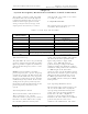
The 335B is made up of the trays and
assemblies listed in Table 2-1.
Table 2-1. 335B Trays and Assemblies
MAJOR ASSEMBLY
DESIGNATOR
TRAY/ASSEMBLY NAME DRAWING NUMBER
A2 AC distribution block
A4 VHF L.B. exciter
1070820 or
1304463 w/Precise Frequency
A5, A6, A7, A9, A11 Five VHF amplifier trays 1304363
A8 VHF combiner assembly 1065241
A13 Harmonic filter 1304390
A14 Bandpass filter assembly 1304388
A12 Remote interface assembly 1083510
(Optional)
A25
Precise Frequency Control Tray
1294-1153(+), 1294-1154(0)
or 1294-1155(-)
VHF L.B. Exciter Tray
The (A4) VHF L.B. exciter tray (1070820)
operates using baseband audio and video
inputs to produce a diplexed, modulated,
and on-channel frequency visual + aural
RF output.
NOTE: If your transmitter contains a
precise frequency kit, a precise frequency
control tray provides the PLL circuits that
connect to the VHF exciter tray w/precise
frequency (1304463) for precise channel
oscillator frequency control. Refer to the
335B precise frequency control system
instruction manual for information on the
precise frequency control tray and
system.
Aural IF Synthesizer Board
The baseband audio, either balanced at
TB1 or composite at J6, and the
subcarrier audio at J4, if present, connect
from the rear of the VHF exciter to (A4)
the aural IF synthesizer board (1265-
1303). The board amplifies and controls
the levels of the three possible audio
inputs and provides a single audio
output. A 4.5-MHz CW signal is
generated using a voltage controlled
oscillator (VCO), onto which the audio is
modulated. This produces the modulated
4.5 MHz output of the board that
connects to the sync tip modulator board.
The board also contains a phase lock loop
(PLL) circuit that maintains the precise
4.5-MHz separation between the aural
(41.25 MHz) and the visual (45.75 MHz)
IF frequencies
Sync Tip Clamp/Modulator Board
The baseband video connects from J1 on
the rear of the VHF exciter to (A5) the
sync tip clamp/modulator board (1265-
1302). The sync tip clamp/modulator
board takes the video, amplifies it,
provides a sync tip clamp circuit and
modulates the video with a 45.75 MHz IF
generated by the IF carrier oven
oscillator or IF VCXO board. The audio