
System Description Chapter 2


100 Watt High Band VHF Transmitter Chapter 2, System Description
420A, Rev. 0 2-4
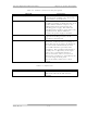
2.1.7 Control and Status
Meters, switches, and LED indicators are
mounted on (A17) the transmitter control
board (1068933). The control board is
attached to the back of the front panel to
allow for the switches and the LEDs to be
operated or viewed from the front of the
tray. The (S1) Operate/Standby switch
controls the output of the transmitter by
applying or removing the inhibit
command to the switching power supply
that provides the DC supply voltages to
the amplifier section.
In Operate, the green LED (DS2) is on
and the inhibit command is removed.
When in Standby, the amber LED (DS1)
is on and the inhibit command is applied.
Switch (S2) is an Automatic/Manual
switch that controls the operation of the
transmitter by the presence of the video
input signal. When the switch is in
Automatic, the green LED (DS3) is lit
and, if the video input signal is lost, the
transmitter automatically switches to
Standby after a short delay. When the
video input signal returns, the
transmitter immediately switches back to
Operate. In Manual, the amber LED
(DS4) is lit and the operation of the
transmitter is controlled by the front
panel switches. During normal operation
of the transmitter, switch S2 should be in
the Auto position.
The front panel of the tray also has LEDs
that indicate Video Fault (Loss) (red LED
[DS9]) and VSWR Cutback (amber LED
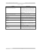
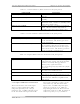
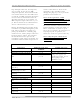
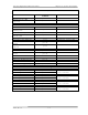
[DS7]). The meters, switches, and LEDs
found in the 420A are described in the
following tables.