
System Description Chapter 2


100 Watt High Band VHF Transmitter Chapter 2, System Description
420A, Rev. 0 2-6
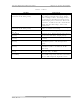
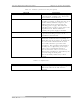
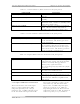
Table 2-2. Switches (mounted on the front panel)
SWITCH FUNCTION
TRANSMITTER (S1) The momentary contact switch (S1) applies
a ground to K1, latching relay, located on
the transmitter control board.
OPERATE/STANDBY K1 will switch either to Operate or to
Standby depending on which direction S1 is
pushed. When switched to Operate, the
inhibit command is removed from the
switching power supply. This allows the
switching power supply to apply 48V to the
amplifier boards. When switched to
standby, the power supply is disabled.
MODE SELECT (S2) The momentary contact switch (S2) applies
a ground to latching relay K2, on the
transmitter control board.
AUTO/MANUAL K2 will switch the transmitter to the
Automatic or Manual mode depending on
which direction S2 is pushed. In Automatic,
the video fault command from the ALC
board will control the operation of the
transmitter. The transmitter will switch to
Standby after a slight delay, if the input
video is lost, and will switch back to
Operate when the video is restored. In
Manual, the transmitter is controlled by the
operator using the front panel
Operate/Standby switch or by remote
control.
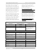
Table 2-3. Adjustments
ADJUSTMENT DESCRIPTION
GAIN (A20-R1) Adjusts the gain of the RF output using the
ALC board when the IF ALC circuit is
Enabled