
System Description Chapter 2


100 Watt High Band VHF Transmitter Chapter 2, System Description
420A, Rev. 0 2-7
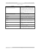
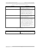
Table 2-4. Control Indicators (LEDs mounted on the front panel)
INDICATOR FUNCTION
OPERATE (DS2 GREEN) Indicates that the transmitter is in
Operate
STANDBY (DS1 AMBER) Indicates that the transmitter is in
Standby
AUTO (DS3 GREEN) Indicates that the transmitter is in
Automatic mode; switches to Standby if the
input video signal is lost
MANUAL (DS4 AMBER) Indicates that the transmitter is in Manual
mode; will not automatically switch to
Standby if the input video signal is lost
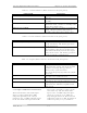
Table 2-5. Status Indicators (LEDs mounted on the front panel)
INDICATOR FUNCTION
VIDEO LOSS (DS9 RED) Indicates that the input video has been lost
to the transmitter. The fault is generated
on the ALC board.
VSWR CUTBACK (DS7 AMBER) Indicates that the reflected power level of
the transmitter has increased above 20%;
this will automatically cut back the output
power level to 20%. The fault is generated
on the transmitter control board.
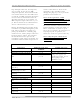
Table 2-6. Samples (BNC connectors mounted on the front panel)
SAMPLE DESCRIPTION
f(s) A sample of the channel oscillator output
taken from the sample jack of the channel
oscillator assembly. The (f
C
) channel
RF frequency equals four times
the crystal frequency (f
S
) minus the (f
IF
) IF
frequency.
f(IF) A sample of the 45.75 MHz output from the
IF carrier oven oscillator board
f(IC) A sample of the 4.5 MHz intercarrier
output from the aural IF synthesizer board
EXCITER O/P An output power sample of the exciter
taken from the VHF filter/amplifier board,
high output
2.1.8 Input and Remote Connections
The baseband video and audio inputs
alone or, if the (optional) 4.5 MHz
composite input kit (1273-1326) is
purchased, the 4.5 MHz composite input
or the baseband video input and audio
input to the transmitter, connect to the
rear of the tray. The baseband video
input, or the 4.5 MHz composite input,
connects to jacks J1 or J2, which are
loop-through connected. The baseband
audio input connects to TB1 for balanced
audio or to jacks J3 or J13, which are