
System Description Chapter 2


100 Watt High Band VHF Transmitter Chapter 2, System Description
420A, Rev. 0 2-9
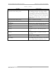
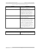
Table 2-7. Remote Interface Connections
FUNCTION REMOTE JACK/PIN
NUMBER
INTERFACE TYPE
Modulator Select (optional) J11-10 Contact closure
Modulator Select Rtn
(optional)
J11-30
Remote Status Indications
Transmitter Operate
(Enable) Ind
J10-3
50 mA max. current sink
Operate/Standby Ind Return J10-16
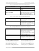
Transmitter Standby
(Disable) Ind
J10-4
50 mA max. current sink
Transmitter Auto Indicator J11-7 50 mA max. current sink
Auto/Manual Indicator
Return
J11-32
Transmitter Manual
Indicator
J11-6
50 mA max. current sink
VSWR Cutback Indicator J11-37 50 mA max. current sink
VSWR Cutback Indicator
Return
J11-35
Video Loss (Fault) Indicator J11-25 50 mA max. current sink
Video Loss (Fault) Ind. Rtn J11-31
Receiver Fault (optional) J11-12
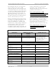
Remote Metering
Visual Output Power J11-26
Visual Output Power Rtn J11-28
1V full scale At 1kΩ
source resistance
Aural Output Power J11-27
Aural Output Power Rtn J11-29
1V full scale At 1kΩ
source resistance
Reflected Power J10-5
Power Rtn J10-22
1V full scale At 1kΩ
source resistance
Exciter Output Power J10-10
Power Rtn J10-22
1V full scale At 1kΩ
source resistance