
User's Manual


SYSTEM 5543A DIGITAL AGILE PAGE 2
CABINET MOUNTING INSTRUCTIONS FOR SLIDES DRAWING
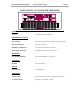
CONNECTIONS
Once all equipment is in place, making connection to the back of the tray (s) is a relatively simple process.
Each wire is clearly marked with a number corresponding to the tray where it connects.
NUMBERING
The numbering system used on wires that connect to the back of the trays is as follows:
FIRST NUMBER - Channel designator
SECOND NUMBER - Connector on back of tray
EXAMPLE: A wire marked 2 10 would go to channel 2 in the group, connector J10
Finally, verify that AC power (J1) is connected to each unit. Once this is complete, proceed to the initial turn
on procedures.
NOTE: All Axcera products are designed for operation with either 115VAC or 208/230 VAC, 50/60 Hz
input. Systems are shipped from the factory properly configured for the standard of the country of destination.