
User's Manual


SYSTEM 5543A DIGITAL AGILE PAGE 3
SYSTEM DESCRIPTION
FREQUENCY GENERATOR TRAY
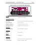
The Frequency Generator tray is configured to control multiple VCXO’s. within the 4 Channel VCXO
assembly. The selected VCXO output is sent to the VHF Buffer/Combiner Board where the RF signal is
amplified. The output of the VHF Buffer/Combiner Board is multiplied by four and filtered, then processed
by the PLL Board. Once again the signal is multiplied and filtered producing an L.O. output to the agile
upconverter. A liquid crystal display on the front panel provides access to various menus through the use of
five soft touch keys.
10-WATT AGILE UPCONVERTER/AMPLIFIER
The 10-Watt Agile Upconverter/Amplifier accepts an input signal of +25 to +35 dBmV and is compatible
with any QAM signal up to 256 and VSB up to 16. Operating frequency range is from 2572-2614 MHz.
The signal is processed through the unit in a similar manner to that of an analog system with IF circuitry
performing ALC, frequency response and delay correction as well as linearity correction. The RF signal is
sampled, peak detected, and fed to a control amplifier before being connected to the output of the tray.