INSTRUCTION MANUAL Axciter Digital Modulator/Upconverter System AXCERA, LLC 103 FREEDOM DRIVE P.O. BOX 525 LAWRENCE, PA 15055-0525 USA (724) 873-8100 • FAX (724) 873-8105 www.axcera.com • info@axcera.
Digital ATSC Exciter-Modulator System Table of Contents CHAPTER 1: INTRODUCTION...................................................................................................................... 1 MANUAL OVERVIEW .......................................................................................................................................... 1 AXCITER OVERVIEW ........................................................................................................................................
Digital ATSC Exciter-Modulator System Table of Contents CHAPTER 4: AXCITER MODULATOR AND TRANSMITTER SET UP PROCEDURES ................... 47 AXCITER ALIGNMENT OVERVIEW .................................................................................................................... 47 TRANSMITTER SET UP PROCEDURES ................................................................................................................ 47 SYSTEM PREPARATION ........................................................
Digital ATSC Exciter-Modulator System Chapter 1, Introduction Chapter 1: Introduction This manual explains the installation, setup, operation, alignment and maintenance for the Axciter 8VSB digital television modulator. It is intended that persons installing, operating, or maintaining the Axciter read this manual for important safety and operational instructions. Manual Overview This instruction manual is divided in 5 chapters and four supporting appendices.
Digital ATSC Exciter-Modulator System Chapter 1, Introduction Axciter. It is important to know what these selections do and when they should be used. The Axciter is designed to work over a wide range of transmitter types and field conditions. There are certain front panel settings that if improperly selected could cause undesired results.
Digital ATSC Exciter-Modulator System Chapter 1, Introduction removed then the airflow will be altered such that some circuits do not receive proper cooling. Servicing Do not attempt to service this product yourself until becoming familiar with the equipment. If in doubt, refer all servicing questions to qualified Axcera service personnel. Replacement Parts When replacement parts are used, be sure that the parts have the same functional and performance characteristics as the original part.
Digital ATSC Exciter-Modulator System Chapter 1, Introduction Warranty for Broadcast Products Limited One-year Warranty Axcera warrants each new product that it has manufactured and sold against defects in material and workmanship under normal use and service for a period of one (1) year from the date of shipment from Axcera’s plant, when operated in accordance with Axcera’s operating instructions. This warranty shall not apply to tubes, fuses, batteries, or bulbs.
Digital ATSC Exciter-Modulator System Chapter 2, Installation and Operating Instructions Chapter 2: Installation and Operating Instructions This section provides information on how to install and set up the Axciter exciter system. Installation To install the Axciter stand alone tray system: If the trays are not pre-installed in a cabinet, follow the steps below. 1.
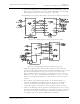
Digital ATSC Exciter-Modulator System Chapter 2, Installation and Operating Instructions 3. Connect the AC power cord, provided in the installation kit, to the AC input jack, located on the rear of the Axciter modulator. Do not plug the AC power cord into a source of power, at this time. The following steps apply to the Axciter tray-based or sled-based system. Figure 2- 2: Block Diagram Axciter tray-based system Figure 2-3: Block Diagram Axciter sled-based system 1.
Digital ATSC Exciter-Modulator System Chapter 2, Installation and Operating Instructions 4. There is a SPDT RF relay, mounted in the upconverter/ downconverter tray, in a tray-based system or externally in a sled-based system, which selects an RF sample from one of two places. The samples are from either before the transmitter output channel mask filter, NonLinear Distortion, or after it, Linear Distortion. These samples are used in the adaptive equalization process.
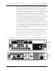
Digital ATSC Exciter-Modulator System Chapter 2, Installation and Operating Instructions On/Off Circuit Breaker Figure 2-6: HX or LX Driver/Amplifier Chassis Assembly, Rear View Table 2-1.
Digital ATSC Exciter-Modulator System MODULATOR TRAY Chapter 2, Installation and Operating Instructions UPCONVERTER TRAY LEVEL CONNECTOR (J16) Post-Filter sample input (Linear Distortion) -10 to 0 dBm (-5 dBm Typical) 50Ω BNC (J17) Pre-Filter sample input (Non-Linear Distortion) -10 to 0 dBm (-5 dBm Typical but within .5 dB of J6 sample level) 50Ω BNC N/A 50Ω BNC (J24) SW A output (Normally jumpered to J4) Table 2-4.
Digital ATSC Exciter-Modulator System Chapter 2, Installation and Operating Instructions Setup and Operation Procedures The initial setup and operation of the ATSC modulator should be performed after the unit has been connected to an external SMPTE 310M source and the Axciter modulator has been connected to the upconverter or to the driver/amplifier chassis.
Digital ATSC Exciter-Modulator System Chapter 2, Installation and Operating Instructions SMPTE 310 Connection The SMPTE 310 input receives a serial ATSC bitstream at a data rate of 19.392658 megabits per second. Line code is biphase mark. Signal amplitude should be 800 millivolts peak to peak when terminated in a 75 ohm load. The SMPTE 310 signal is internally regenerated and reclocked by the Axciter modulator, and is available for testing or other uses at the connectors on the rear panel.
Digital ATSC Exciter-Modulator System Chapter 2, Installation and Operating Instructions The Color of values and fields indicate status. Graphs are used to display DTVision analysis. The top level menu structure has 5 options: 1. Control/Status 2. DTVision Linear (if installed) 3. DTVision Nonlinear (if installed) 4. Upconverter 5. Setup Example of screen is shown below. Screens for Control/Status Access the Control/Status screens by pressing the top soft button from the main screen.
Digital ATSC Exciter-Modulator System Chapter 2, Installation and Operating Instructions Screens for DTVision Linear Access the DTVision Linear screens by pressing the second soft button on the Main Status screen. DTVision Linear screens are listed in Table 2-5. Table 2-5. ATSC Screens SCREEN DESCRIPTION DTVision Linear Home (Spectrum) See page 22 for more information. DTVision Const See page 24 for more information. DTVision Eye See page 25 for more information.
Digital ATSC Exciter-Modulator System Chapter 2, Installation and Operating Instructions Fields Buttons on the Screen Buttons on the Front Panel Home When Home is pressed, you are taken back to the home screen. Back Back is used to return to the previous screen. Help When the help button is pressed, the help screen relevant to the screen you were on at the time you pressed ‘Help’ is presented.
Digital ATSC Exciter-Modulator System Chapter 2, Installation and Operating Instructions Screen Displays and Details Axciter Main Screen The purpose of this display is to show the general status of the Axciter. Legend Green: The green value indicates that there are no errors and everything is normal and present. Red: The red value indicates there are errors or problems. Yellow: The yellow indicates the associated value is absent or not on or is at a warning level.
Digital ATSC Exciter-Modulator System Chapter 2, Installation and Operating Instructions Operate/Standby: States whether the Axciter is in standby or operate. This is controlled by a system controller if there is one. Status: Summary fault status of the exciter. See Control/Status page for more details. Control and Status Screen The purpose of this display is to show the general status of the Axciter. Status SMPTE Lock: Indicates whether the SMPTE sync packets are detected.
Digital ATSC Exciter-Modulator System Chapter 2, Installation and Operating Instructions Signals Status Screen Signals +310 Select: Displays which 310 input is being used on air. Channel Offset: Displays whether an offset is in use. Channel Offset Type: Displays the type of offset selected. Channel Offset User Value: The amount of manual offset selected. NDDS Value: An internal raw reading used for 310 clocking. 310 Frequency Error: The calculated frequency error of the active 310 input.
Digital ATSC Exciter-Modulator System Chapter 2, Installation and Operating Instructions Channel Offset Example CHANNEL OFFSET Enable Selecting this option will change the transmitted frequency by the selected offset value. (Channel offsets are used to minimize co-channel or adjacent channel interference.) Disable Selecting this option will set the transmitted frequency to the standard value for the channel in use (pilot 309.440559 kHz above the lower channel edge.
Digital ATSC Exciter-Modulator System Chapter 2, Installation and Operating Instructions Manual If research into channel offsets produces new values that can mitigate certain interference conditions, any channel offset value can be entered in the box. None Disables channel offset. Select this box to transmit without any channel offset. AXACT Equalizers Axcera Axciter, Rev.
Digital ATSC Exciter-Modulator System Chapter 2, Installation and Operating Instructions LINEAR EQUALIZER Hold When this option is selected, the linear equalizer is forced to use the current values rather than calculating new values. This will continue until the Hold option is deselected. The equalizer will not adjust to compensate for changes while this is selected.
Digital ATSC Exciter-Modulator System Chapter 2, Installation and Operating Instructions Nonlinear Failures This value shows the number of times since Axact started that Nonlinear Adaptive was unable to use the data available to fix the equalizer. Clock and Power Status Screen Clock Power 10MHz: External reference presence indication. 1GHz: Lock status of internal 1GHz clock oscillator. IF Out Level 1: Level of 12VDC source. IF Out Level 2: Level of 12VDC source.
Digital ATSC Exciter-Modulator System Chapter 2, Installation and Operating Instructions -12V Supply: Voltage of regulated -12VDC source. +5V Supply: Voltage of regulated +5V source. Coder +3.3V: Channel Coder's 3.3V voltage regulator output. Mod +3.3V: IF +3.3V: Modulator board's 3.3V voltage regulator output. IF board's 3.3V voltage regulator output. LED Status Screen LED Status Screen gives a user a view of the LEDs both on the front of the Axciter as well as the rear.
Digital ATSC Exciter-Modulator System Chapter 2, Installation and Operating Instructions Front Panel LEDs LED FUNCTION Power On Air Input IF Output PLL Lock SMPTE Lock Adaptive Input Communication Link Fault Number Lock Indicates the keypad types numbers only, arrows do not work. Rear Panel LEDs The rear panel of the modulator has an LED next to each coaxial connector. During operation, a green LED next to the connector means that the signal is present.
Digital ATSC Exciter-Modulator System Chapter 2, Installation and Operating Instructions History Axact Restarts This value lists the number of times the AXACT sub-program has restarted. This may indicate a problem with communications and/or hardware. ConStat Connections This value lists the number of times the ConStat server has reconnected to the Netburner computer. This may indicate a problem with communications and/or the Netburner itself.
Digital ATSC Exciter-Modulator System Chapter 2, Installation and Operating Instructions DTVision Linear - Optional This section contains information regarding the DTVision Screens. These screens are optional diagnostic screens. They are not necessary for the operation of the Axciter. However, they greatly enhance the experience. These graphs provide the same type of views as an EFA. All of the Linear Screens have the following reference values on the bottom of the screens.
Digital ATSC Exciter-Modulator System Chapter 2, Installation and Operating Instructions and/or the DAC. If this happens, lower the unity gain reference point for the nonlinear equalizer. Peak to Average Ratio This value shows the peak to average ratio of the transmitted signal. This value is typically 6 to 8 dB for a perfect signal. A value significantly lower will indicate peak compression. A small amount of peak compression is normal.
Digital ATSC Exciter-Modulator System Chapter 2, Installation and Operating Instructions DTVision Constellation Screen I & Q Constellation Display This display is created by plotting the 8-VSB in-phase (I) component against the quadrature (Q) component. When the samples are taken at the symbol time, then the data points will be precisely aligned along the eight vertical lines. Those eight vertical lines are the eight VSB data levels. Axcera Axciter, Rev.