
User's Manual


Digital ATSC Exciter-Modulator System Chapter 2,
Installation and Operating Instructions
Axcera Axciter, Rev. 0 6
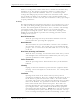
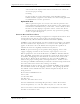
3. Connect the AC power cord, provided in the installation kit, to the AC
input jack, located on the rear of the Axciter modulator. Do not plug
the AC power cord into a source of power, at this time.
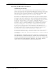
The following steps apply to the Axciter tray-based or sled-based system.
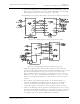
Figure 2- 2: Block Diagram Axciter tray-based system
Figure 2-3: Block Diagram Axciter sled-based system
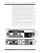
1. Using the supplied cables and any other cables needed, make the
necessary interconnections between the Axciter modulator tray and the
upconverter/downconverter tray, in a tray-based system or the
driver/amplifier chassis assembly, in a sled-based system. Refer to
Figures 2-4, 2-5 & 2-6, the information in Tables 2-1, 2-2, 2-3 & 2-4
and the preceding block diagrams to aide in the reconnection of the
system.
2. The required external interconnections are detailed in Table 2-3.
Connect the SMPTE 310M signal source to the J27 or J23 input as
selected on the front panel of the Axciter modulator tray. This
connection applies to both the tray-based and sled-based systems
3. Connect the RF output of the upconverter/downconverter tray at J8 to
the driver or IPA of the transmitter, in a tray-based system. In a sled-
based system, connect the RF output of the driver/amplifier chassis
assembly at J25 to the driver or IPA of the transmitter