
User's Manual

4
5
2) Peak surge current: 15 sec max.
Measurements shall be made with an oscilloscope with 20MHz bandwidth. 10uF elec
trolytic capacitor parallel 0.1uF ceramic capacitor to simulate system loading to measure
it.
3) At peak load +12V output regulation +/-10%.
2.1 HOLD-UP TIME: 20ms (minimum)
Test Condition: Full load. AC input 115V or 230V, 60Hz or 50Hz
2.2 LOAD TRANSIENT RESPONSE (STEP LOAD)
Step load changes up to 20% of full load, while other loads remains constant within the
rating. The load waveform shall be a square wave with the slope of the rise and fall at
0.1A/usec and the frequency shall be from 10Hz to 1 kHz. The DC output voltage will
stay within regulation during the step load changes.
2.3 OVERSHOOT
Overshoot at turn on or turn off shall be less than 10% of the nominal output voltage.
3.0 PROTECTION:
If the power supply latches into shutdown stage (when over current, over voltage or
short circuit protection is working), the power supply shall return to normal operation
only after the fault has been removed and PS-ON is reset for a minimum of 1 Second
or remove AC power is removed and re-applied.
3.1 OVER CURRENT PROTECTION
Overload currents applied to each tested output rail will cause output trip before they
reach or exceed 110% ~ 150% for testing purposes. Overload currents should be ramped
at a minimum rate of 10 A/s starting from full load.
3.2 OVER VOLTAGE PROTECTION
3.3 SHORT CIRCUIT PROTECTION
All output to GND.
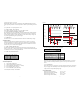
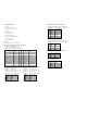
4.0 TIME SEQUENCE:
T1 Turn On Time (500ms max.)
T2 Output Voltage Sequencing (20ms max.)
T3 Power Good Delay Time (100ms < t3 <500ms)
T4 Power Fail Delay Time (1ms min.)
T5 Power Good Hold-Up time (20ms min)
115V/230V(FULL LOAD): 1ms minimum
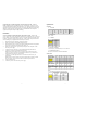
SENSE LEVEL OVER VOLTAGE
+5V 6.5V/max.
+12V 15.6V/max.
+3.3V 4.1V/max.
AC-V
AC-ON
AC-OFF
PS-ON
HIGH
LOW
T1
T2
T3
T5
T4
TURN-ON
POWER GOOD
ON-RING
OFF-RING
POWER FAIL
HIGH
HOLD-UP
P.G. WAVE FORM
VB= 4.75V
+5V Wave Form
4.1 REMOTE ON/OFF CONTROL
The power supply is turned on or off by TTL signal.
Remote On/Off Signal Characteristics
4.2 AUXILIARY +5VSB
This power supply is specifically equipped with an independent stand-by +5V output
current, 2.0A max. This output will always provide +5V except when the AC line is
cut-off.
4.3 AUTO RESTART
If the output of the power supply drops out of the regulation caused by AC line Voltage,
the power supply will automatically resumes normal operation only after the AC line
voltage returns to the specified operating range.
5.0 ENVIRONMENT:
Ambient operation temperature 10°C to +50°C
Ambient operation relative humidity 20% to 85%
Ambient storage temperature -40°C to +70°C
Ambient storage relative humidity 10% to 95%
Figure 1.
Active low Power supply turn on
Active high Power supply turn off
PS-ON MIN MAX
Vil, input low voltage 0.8V
Vil, input low current, Vin=0.4V -1.6mA
Vih, input High voltage, lin=-200uA 2.0V
Vih open circuit, lin=0 5.25