
User's Manual


Innovator CU250ATD, 250 Watt Transmitter Table of Contents
Instruction Manual, Rev. 0 August 14, 2007
CU250ATD INNOVATOR 250-WATT TRANSMITTER
Introduction ..................................................................................................1
Manual Overview .....................................................................................1
Assembly Designators ..............................................................................1
Safety ....................................................................................................1
Contact Information.................................................................................2
Return Material Procedure ........................................................................2
Warranty Information...............................................................................3
30W Driver Tray Description .........................................................................10
8 VSB Demodulator Board ......................................................................10
8 VSB Modulator Board ..........................................................................10
Amplifier Assembly ................................................................................11
2 Stage UHF Amplifier Board, ...........................................................12
RF Module Pallet w/Philips Transistors ...............................................12
Output Detector Board ...........................................................................12
30W Driver Tray Power Supplies .............................................................13
30W Driver Tray LCD Display and Front Panel LED Indicators ...........................13
30W Driver Tray Input and Output Connections...............................................14
30W Driver Tray Remote Connections ............................................................14
Front Panel Screens for the Transmitter..........................................................16
250W Power Amplifier Tray Description ..........................................................19
2-W ay Splitter ......................................................................................19
600W PEP RF Pallet................................................................................19
2-Way Combiner ...................................................................................19
Amplifier Control Board ..........................................................................19
+12VDC Switching Power Supply ............................................................19
+30VDC Switching Power Supply ............................................................19
250W Power Amplifier Input and Output Connections.......................................20
System Alignment...................................................................................................21
Set Up of the Output Power of the Transmitter..........................................21
ALC Board Set-Up in the Transmitter .......................................................21
Linearity Correction Adjustment ..............................................................22
Frequency Response Delay Equalization Adjustment..................................22
Appendix A
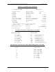
Drawings List..............................................................................................A-1
Transmitter Specifications............................................................................B-1