
User's Manual


350-Watt VHF LB Digital Transmitter Chapter 1, Introduction
DT325B, Rev. 0 1-1
Chapter 1
Introduction
This manual explains the installation,
setup, alignment, and maintenance
procedures for the DT325B 350-watt
digital VHF low band transmitter. It is
important that you read all of the
instructions, especially the safety
information in this chapter, before you
begin to install or operate the unit.
1.1 Manual Overview
This instruction manual is divided into
five chapters and supporting appendices.
Chapter 1, Introduction, contains
information on safety, the Axcera method
of assigning assembly designation
numbers, maintenance, return
procedures, and warranties. Chapter 2
describes the transmitter and its system
control and status indicators and remote
control connections. Chapter 3 explains
how to unpack, install, set up, and
operate the transmitter. Chapter 4,
Circuit Descriptions, describes the circuits
that make up the trays and assemblies in
the transmitter. Chapter 5, Detailed
Alignment Procedures, provides
information on adjusting the system
assemblies for optimal operation.
Appendix A contains the system
specifications sheet. Appendix B
contains the system drawings and parts
lists. Appendix C contains the assembly
and subassembly drawings and parts lists
for the exciter/driver chassis and
modules. Appendix D contains the
drawings and parts lists for the VHF Low
Band Amplifier Tray and the assemblies
and subassemblies that make up the
tray.
1.2 Assembly Designation Numbers
Axcera has assigned assembly numbers,
Ax designations such as A1, where
x=1,2,3…etc, to all assemblies, modules,
and boards in the system. These
designations are referenced in the text of
this manual and shown on the block
diagrams and interconnect drawings
provided in the appendices. The Block
Diagrams, Interconnects, Schematics,
Assembly Drawings and Parts Lists are
arranged in increasing numerical order in
the appendices. Section titles in the text
for assembly or module descriptions or
alignment procedures contain the
associated part number(s) and the
relevant appendix that contains the
drawings for that item.
The cables that connect between the
boards within a tray or assembly and
that connect between the trays, racks
and cabinets are labeled using Brady
markers.
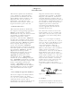
Figure 1-1 is an example of a Brady
marked cable. There may be as few as
two or as many as four Markers on any
one cable. These Brady markers are
read starting furthest from the
connector. If there are four Brady
Markers, this marker is the transmitter
number such as transmitter 1 or
transmitter 2. The next or the furthest
Brady Marker is the rack or cabinet
number on an interconnect cable or the
board number within a tray. The next
number on an interconnect cable is the
Tray location or number. The Brady
marker closest to the connector is the
jack or connector number on an
interconnect cable or the jack or
connector number on the board within a
tray.
Figure 1-1 Brady Marker Identification
Drawing
1.3 Safety
The DT325B transmitters manufactured
by Axcera are designed to be easy to use