
User's Manual Part 2


Digital ATSC Exciter-Modulator System Chapter 2,
Installation and Operating Instructions
Axcera Axciter, Rev. 0 35
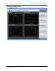
Nonlinear Equalizer Display
Nonlinear Equalizer Display:
This display shows the nonlinear corrections being applied to the signal to
correct for the RF power amplifier’s envelope compression and incidental
phase modulation. The horizontal axis is the ideal RF envelope magnitude. The
yellow magnitude trace shows the instantaneous gain correction being applied
to the signal as a function of the desired envelope amplitude, to correct for
amplitude compression in the power amplifier. The red phase trace shows the
amount of phase correction being applied to correct for the power amplifier’s
incidental phase modulation.
As the ideal amplitude becomes large (corresponding to the right part of the
display), the probability density function of the ideal envelope magnitude
becomes very small or zero. So, data in the right hand portion of the display
will generally be extrapolated. Also, the magnitude equalization characteristic
may also drop off, to accomplish clipping and to prevent overflow of the data
feeding the DAC.