Digi-Cool Industries Ltd. Digital Refrigeration System Analyzer AK900 User manual To take full advantage of your analyzer, please read this manual and store in a safe place for future reference. v1.
Table of Contents Table of Contents................................................................................. 2 Package Contents ................................................................................. 3 Features and Use .................................................................................. 4 General ............................................................................................ 4 Proper Use..........................................................
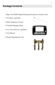
Package Contents 1 Digi-Cool AK900 Digital Refrigeration System Analyzer Unit 1 9V battery (installed) 1 Dual Temperature Sensor 1 Extended Hanging Hook 1 Two valve ball valve manifold 1 User Manual 1 Product Registration Card
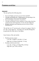
Features and Use General The unit performs the following tasks: • • • • • Sense and display pressures present in the manifold Calculate and display dew / bubble points corresponding to the sensed pressures, for the selected refrigerant Sense and display temperature of probe tip Calculate and display system superheat or subcooling, based on sensed pressure and temperature, for the selected refrigerant Displays maximum and minimum pressures observed since threshold reset The unit has two 1/8" pressure p
• • • • • • • • • • • • Includes profiles for 45 common refrigerants "Dynamic Offset" bar graph display Pipe-mounted temperature probe for automatic superheat and subcooling readings MAX and MIN pressure monitoring for control set-up Zero key automatically calibrates to local atmospheric conditions Large, easy to read LCD display Adjustable LCD display contrast Selectable reading update rates of 1 and 5 seconds, or hold current reading Upgradeable to handle additional refrigerants Automatic shutdown afte
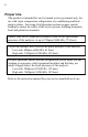
Proper Use This product is intended for use by trained service personnel only, for use with vapor compression refrigeration, air conditioning and heat pump systems. Servicing of refrigeration systems require special training to ensure the safety of the service person, building occupants, local and global environment. Ensure your service manifold is properly rated for the operational pressures of the analyzer, at up to 550psia (3000 kPa, 37.9 bars).
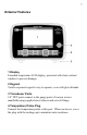
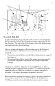
External Features 1 Display Extended temperature LCD display, protected with clear resilient window to prevent damage. 2 Keypad Tactile response keypad is easy to operate, even with gloved hands. 3 Transducer Ports 1/8" NPT ports connect to the gauge ports of various service manifolds using supplied street elbows and swivel fittings. 4 Temperature Probe Plug Connect the temperature probe to this port. When not in use, cover the plug with the sealing cap to maintain water resistance.
5 Vent Allows for atmospheric and internal pressure adjustment without moisture entry. Do not cover this port. 6 Temperature Probe The temperature probe can be secured onto piping from 3/8” to 3” in outer diameter (1 to 7.5cm) with the attached hook-n-loop strap. The connectors are water resistant when mated or when covered by their protective caps. For accurate measurements, use a piece of pipe insulation over the sensor and pipe to insulate them against the ambient air.
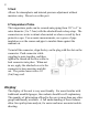
1 Low and High Side In general, displays on the left side of the screen are associated with the low-pressure side of the refrigeration system, represented by the blue labeling. The right side of the display reflects the high-pressure side, represented by the red labeling.
reading. Given the wide operating range of the analyzer, extremely accurate vacuum readings are intrinsically difficult to achieve. When no pressure unit is indicated, the amounts shown are in bars. 2 Dynamic Offset Bar Graph Each bar graph represents changes to each pressure reading since the digits were updated. The graphs are updated four times every second. They allow the user to monitor pressure dynamics in the system closely. Each segment in the low side bar graph represents ¼ psi (2 kPa, 0.
5 Selected Refrigerant The currently selected refrigerant is shown here. The characteristics of the selected refrigerant are reflected in the temperature readings discussed above.
R427A R428A R434A R437A R438A R500 R502 R507 R508B R600A R-427A 52 45 49 99 500 502 50 95 600A RS-45 500 502 AZ-50 Suva 95 600A (Isobutane) If the "R" prefix is visible, the ASHRAE reference number is being shown. If "R" prefix is not visible, the number shown is the numeric portion of the refrigerant's trade name, as shown below. The user may change the set of names displayed by holding "R-" during power up.
9 SuperHeat This character set of the display is the superheat reading, in either °F or °C. If temperature reading lower than the low-side dew point for the selected refrigerant, SH is negative. 10 SuperHeat Temperature (lowside sensor) The is the actual temperature being measured by the Superheat sensor on the line it is mounted on. 11 SubCool Temperature (highside sensor) This is the actual temperature of the highside sensor on the line it is mounted on.
R- / These keys select between available refrigerants. When the last available refrigerant has been reached, the first one is shown again. If the unit has been upgraded with additional refrigerants, they will be shown following the original refrigerants. Refrigerants are labeled according to their ASHRAE designations or trade numbers. • To change between ASHRAE and trade number display, hold R- while pressing PWR when turning the unit on. ZERO Depress this once to calibrate the unit.
For example, if the update time selected is 1SEC, the pressure and temperature displays are updated every second. With 5SEC, the display is updated every 5 seconds. If the update time selected is HOLD, the temperature and pressure readout are held at the readings when HOLD was initiated. In HI and LO pressure recall modes, only 1SEC setting is available. Regardless of the update period, the bar graph updates automatically 4 times per second.
Using the Pressure Gauges Once mounted properly onto a service manifold, the pressure gauges behave just like traditional needle pressure gauges. Usually, the low side of the manifold is connected to the low-side service port, and the high side of the manifold to the high-side service port. Using Pressure Recall Modes The pressure recall modes are useful when setting switching equipment and observing load changes over long periods.
Once the temperature probe is connected to the analyzer, the system automatically enters t mode after several seconds. Several operation modes are then available through the MODE key: t mode The temperature of the probe is shown on the lower right, following t. It is in ºF or ºC, depending on the unit selected. Depending on the measurement and sensor contact, it takes 30 seconds to 2 minutes for the sensor to settle to the correct temperature reading.
The absolute zero function This gives the 900 the ability to zero the pressure readouts to absolute zero and thus read out accurately in high altitude locations. In order to take advantage of this function you will need to put the 900 into the o F/psia mode and then with both the low side and high side connected to a vacuum pump at 100 microns or less (the lower the better); press the zero key and hold it down for 4 seconds.
Specifications Sensing resolution: Low side: High side: 0.25psi (2kPa, 0.02bars) 1psi (7 kPa, 0.07 bars) Sensing accuracy: 0.6% FS ± 1 least significant digit Working pressure: Low side: High side: 0-200psia (1350 kPa, 13.5 bars) 0-550psia (3000 kPa, 37.
Care & Maintenance General Care Follow these basic precautions to ensure that your analyzer will perform well for years to come: • • • • • • • Do not push keys with sharp objects Do not expose the unit to extreme heat, or leave in direct sunlight for extended periods of time. Do not leave the unit in contact with water or other fluids for extended periods of time. Do not immerse the unit in liquids. Do not pull on the temperature probe cord. Avoid rapidly heating or cooling the unit.
back half of the case. 8. Replace the back cover and install screws, while taking care not to crush internal cabling. Reinstall boot if desired. If the unit will not be used for several months, remove batteries from the unit. Do not heat or open battery. A battery not designed to be recharged can leak or rupture if recharged. Where facilities exist, alkaline batteries can be recycled. Cleaning Do not use harsh acids or bases to clean the unit.
Calibration The unit is calibrated to stated accuracy during manufacturing. The absolute accuracy of the calibration is traceable to the U.S. National Institute of Standards and Technology (NIST). The measurements will perform within the specified accuracy over its life. No calibration is necessary. If the unit gives erroneous readings, please return to the manufacturer for service.
Troubleshooting If the unit is not performing properly, please use this troubleshooting chart. Try the listed actions under the appropriate problem, in order from top to bottom until the problem is resolved. If these steps do not correct the problem, please contact the manufacturer for service. Symptom No display when PWR pressed Action • • • • Strange characters or patterns seen on display • • • • • Increase LCD contrast. If no response, press PWR and try increasing contrast again.
Display flashes • • You may be exceeding the 200psia and 550psia working ranges, or selected a refrigerant unsuitable for the current pressure reading. Disconnect pressure connection to system, press ZERO to recalibrate LCD has dim contrast • • Press LCD ↑ to increase contrast Replace batteries with a fresh set Display visibly cracked • Contact the manufacturer for service Condensation inside display window • • Allow unit to warm to ambient temperature.
End-of-Life Disposal Contemporary electronic assemblies such as this unit contain trace amounts of lead, which is harmful to the environment if not properly disposed of. Also, much of the plastic case is recyclable where facilities exist. Digi-Cool Industries supports the proper disposal of this product at the end of its service life. New companies and initiatives to collect electronic products for disposal are underway around the world.
Warranty Digi-Cool Industries Ltd. Limited One Year Warranty What is covered This warranty covers any defects in materials or workmanship in your new analyzer, with the exceptions stated below. How long coverage lasts This warranty lasts for 1 year after purchase date. Coverage terminates if you transfer ownership of the product to another party during the warranty period.
Maintenance" sections of this manual for details on for the proper use and parameters of the analyzer. GUYS IF YOU USE YOUR TEMPERATURE SENSORS TO PULL YOUR 4X4 OUT OF AXLE DEEP MUD..WE WON’T WARRANTY THEM! (the sensor leads have been selected as a fine wire so as not to channel heat into the tiny delicate sensor and give your false readings. The downside of these as opposed to our previous ‘truck pullers’ is that they are quite delicate.
Digi-Cool's obligation under this limited warranty is strictly and exclusively limited to the repair or replacement free of charge of such articles found to be defective in material or workmanship, or to refund the full purchase price upon the return of the defective article, on the condition that the purchaser gives prompt written notice to Digi-Cool of any claim under this warranty period within the two year warranty period and, if requested, returns the defective articles to Digi-Cool.
This warranty is governed by and will be construed in accordance with the laws of British Columbia, Canada, without reference to any rules of conflict of laws. The Courts of British Columbia will have jurisdiction over all claims, disputes and actions related to or arising from or out of or in connection with the warranty and the purchased product, and Digi-Cool and all purchasers hereby irrevocably attorn to the jurisdiction of those courts.
Service and Support If you experience problems with the use of your analyzer, please read the features and troubleshooting sections of this manual. Should your analyzer require service, you may return it to Digi-Cool Industries. Contact Digi-Cool Industries for a return authorization (RA) number. Once we receive your unit, the repaired unit or a replacement will be sent to you within 10 business days.
Return for Service Please contact us before you return your unit for servicing.