Eagle & Eagle X Owners Manual
EAGLE & EAGLE X Overview 1 . 8 0 0 . Infrared 5 4 7Printer . 5 Port 7 4 0 • W W W .Worklight U E i T E S T .
Display Parameters On UEi Combustion Analyzers • TF = Flue Temperature: Calculate net temperature in °F or °C. - Shows ambient temp after fresh air calibration and ‘- O C - ’ when probe is disconnected. • T = Net Temperature: - Differential of flue temperature minus ambient (or inlet) temperature - Differential of T1 - T2 • T∆ = Temperature Differential: • O2 = Oxygen: O2 percentage displayed • CO = Carbon Monoxide: CO ppm (parts per million) displayed.
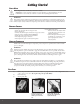
Getting Started Safety Notes Before using this meter, read all safety information carefully. “WARNING” is used to indicate conditions or actions that may pose physical hazards to the user. “CAUTION” is used to indicate conditions or actions that may damage this instrument. WARNING! This analyzer extracts combustion gases that may be toxic in relatively low concentrations. These gases are exhausted from the back of the instrument. This instrument must only be used in well-ventilated locations.
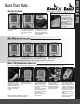
Getting Started Worklight and Display After the Analyzer has zeroed turn test selector to appropriate test screen. Press “s“UP at any point to turn on the backlit display and worklight. NOTE: backlight does not work in the fuel menu.or during purge. Turn Power on in area of fresh air and allow to countdown Rotate test selector to Fuel. Press “s“UP or “t“DOWN to scroll and select desired fuel. Top line is selected fuel. Quick Start Guide Quick Start Guide .
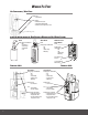
Differential Temperature Test This test is useful for quick checks of temperature rise, and differential/delta T along with other HVAC temperature applications. Rotate test selector to Temp Connect flue probe thermocouple or accessory thermocouple connector to T1. Connect accessory thermocouple probe to T2. Compatible with any K-Type thermocouple probe or clamp. Place thermocouples in test locations to start testing. Observe T1, T2 and Differential/delta T.
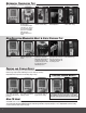
Great for checking for ambient CO and back drafting situations. No probes or hose connections required for this test. Place handset in the area to be tested. Rotate test selector to Room CO Press the PUMP button to start the test. CO readings will be logged every 2 minute for a 30 minute time span To view results rotate test selector to “MENU” and select “REPORT” Scroll to “ROOM CO” and press “SEND”. Press “SEND” to VIEW results. Press “SEND” again to print.
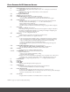
Main Menu Navigation Use the “s“UP or “t“DOWN buttons to scroll through the MAIN MENU or OPTIONS. Press “SEND” to select displayed screen choice. NOTE: Rotate the selector off menu at any time to EXIT. Selections will NOT be saved unless you press “SEND” PRESS “s“UP to scroll through menu items in this order. press “s“ press “s“ MAIN MENU SUB MENU OPTIONS Notes SETUP SET TIME Use to set current time. SET DATE Use to set current date. C < - - -> F ˚F or ˚C Use to select temperature scale.
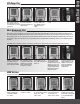
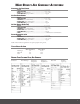
WHAT RESULTS ARE GENERALLY ACCEPTABLE Atmospheric Gas Fired Burners • • • • Oxygen ....................................................................................... Stack Temperature ................................................................... Draft (Water Column Inches).................................................... Carbon Monoxide (parts per million) ....................................... Gas Fired Power Burners • • • • • Oxygen .......................................................
WHERE TO TEST Air Conditioning / Heat Pump Suction Line: • Temperature Verify proper: • Static Duct Pressures • Temperature Differential • Static Pressure Drop Across Coils to condensing unit Boiler & Water Heaters & High Efficiency Modulating Hot Water Systems Boiler Verify proper combustion: • O2 • CO Air Free • Stack Temp • Stack Draft • SSE Water Heater Draft Verify proper combustion: • O2 • CO • Stack Temp • Efficiency HE Boiler Instant Water Heaters Draft Verify proper combustion: • O2 • CO • Stac
Furnaces (continued): Atmospheric, Gas & Oil Atmospheric Furnace Draft Verify proper • Temperature Rise • AC side Static Pressure Drop across coils Verify proper combustion: • O2 • CO • Stack Temp • Efficiency Natural Gas & Propane Verify proper combustion: • O2 • CO • Stack Temp • Vent Pressure • Efficiency Test • Limit Switch • Pressure Switch Set Up • Gas Pressure Verify proper: • Static Duct Pressure • Temperature Rise • AC side Static Pressure Drop across coils Oil Furnace Verify proper combustion:
Other Important Factors Relating To Combustion • The three T’s of combustion – Time • Amount of time that the fuel and oxygen are together in the combustion chamber – Temperature • How high the temperature is determines the rate of oxidation, or speed of the combustion – Turbulence • How well the fuel and air are mixed • These three factors are all interrelated, and will move your results along the combustion curves.
version has been ignored. This loss is subtracted from the efficiency. CO Air Free Certain standards ( ANSI Z21.1) for Carbon Monoxide are stated in terms of air-free. Air-free refers to the concentration of CO in combustion gases undiluted with flue, or other gases containing little CO. This value is computed using an equation that takes into account the O2 concentration of the flue gas. • If 5% O2 is measured (O2m) in the flue then the CO gas value will be recalculated as if 0% were measured.
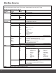
GENERAL Maintenance General Maintenance • Calibrate your instrument annually to ensure it meets original performance specifications • Keep your instrument dry. If it gets wet, wipe dry immediately. Liquids can degrade electronic circuits • Whenever practical, keep the instrument away from dust and dirt that can cause premature wear • Although your instrument is built to withstand the rigors of daily use, it can be damaged by severe impacts.
Batteries Replacement This meter has been designed for use with both alkaline and rechargeable Nickel Metal Hydride (NiMH) batteries. No other types are recommended. The analyzer is supplied with 4 “AA” size alkaline batteries. These should be installed into the instrument as shown in the diagram to the right and indicated on the back of the unit.
EAGLE SPECIFICATIONS C125 C127 C155 C157 Temperature Measurement Flue Temp Range 20~2400˚F (-29~1315˚C) Inlet Temperature (probe - T2) 20~2400˚F (-29~1315˚C) Inlet Temperature (ambient) 32~112˚F (0~50˚C) Net Temperature (_T)** 20~2400˚F (-29~1315˚C) Resolution 0.1˚C/F Flue (T1, Inlet T2 & _T) Accuracy ±(0.3% rdg +3.6˚F(2˚C)) Inlet Temperature Accuracy ±(0.3% rdg +1.8˚F(1˚C)) Gas Measurement Oxygen 0~21%* 0~21%* 0~21%** 0~21%** O2 resolution / accuracy 0.1% / ±0.2% 0.1% / ±0.2% 0.1% / ±0.3% 0.