
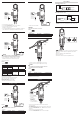
Install Instructions

OVERVIEW
INSTRUCTION MANUAL
ENGLISH
DL220
1-800-547-5740
www.ueitest.com • email: info@ueitest.com
CATIV Clamp Meter and
Voltage Tester
17254 • 1116
FEATURES
• 600V AC/DC
• 200A AC
• Resistance 2000Ω
• Audible continuity
• LRA Inrush
• Sliding clamp
• Auto hold
• Auto ranging
• Backlight
• Low battery indicator
• Auto power off
• Permanent test leads
• Auto calibration
• Latches for battery compartment
• Storage for test leads
• Auto-on
GENERAL SPECIFICATIONS
• Operating Temperature: 32˚ to 104˚F (0˚ to 40˚C)
• Storage Temperature 14˚ to 122˚F (-10˚ to 50˚C)
• Operating Humidity: <75%
• Operating Altitude: 6,562ft (2,000m)
• Pollution Degree: 2
• Display: 3 1/2” 2000 count
• Backlight: Yes
• Refresh Rate: 3/sec
• Over-range: “OL” is displayed
• Dimensions: 8.66” X 2.72” X 1.56”
• Item Weight: 12 oz
• Calibration: Recommended annually
• CAT Rating: CATIV 600V
• Certifications: cETLus 3rd Edition, CATIV 600V, CE Conformity, IP41,
RoHS Compliant, 6’ Drop Protection, IEC 61010-1 3rd Edition
• Battery Type: 1.5V (AAA) X 2
• Accuracy: ± (% of reading + # of least significant digits)
IMPORTANT SAFETY WARNINGS
WARNING
Read entire Safety Notes section regarding potential hazard and proper
instructions before using this meter. In this manual the word “WARNING” is
used to indicate conditions or actions that may pose physical hazards to the
user. The word “CAUTION” is used to indicate conditions or actions that may
damage this instrument.
WARNING
To ensure safe operation and service of the tester, follow these instructions.
Failure to observe these warnings can result in severe injury or death.
WARNING
• Before each use, verify meter operation by measuring a known voltage
or current.
• Never use the meter on a circuit with voltages that exceed the category
based rating of this meter.
• Do not use this meter during electrical storms or in wet weather.
• Do not use the meter or test leads if they appear damaged.
• Keep fingers away from the metal probe contact when making
measurements. Always grip the leads behind the finger guards molded into
the probe.
• Use caution when working with voltages above 60V DC or 25V AC RMS.
Such voltages pose shock hazards.
• To avoid false readings that can lead to electrical shock, replace
batteries if a low battery indicator appears.
• Unless measuring voltage or current, shut off and lockout power before
measuring resistance or capacitance.
• Always adhere to national and local safety codes. Use proper personal
protective equipment (PPE) to prevent shock and arc blast injury where
hazardous live conductors are exposed.
• Always turn off power to a circuit or assembly under test before cutting,
unsoldering or breaking the current path. Even small amounts of current
can be dangerous.
• Always disconnect the live test lead before disconnecting the common
test lead from the circuit.
• In the event of electrical shock, ALWAYS bring the victim to the
emergency room for evaluation, regardless of victim’s apparent recovery.
Electrical shock can cause unstable heart rhythms that may need
medical attention.
• If any of the following occur during testing, turn off the power source to
the circuit being tested: arching, flame, smoke, extreme heat, smell of
burning materials or discoloration/melting of components.
WARNING
Higher voltages and currents require greater awareness of physical safety
hazards. Set meter to desired function prior to applying test leads to a live
circuit. If an erroneous reading is observed: disconnect test leads
immediately, recheck all settings and connections before testing again.
WARNING
Do not change function on the meter while test leads are connected to a live
circuit.
WARNING
This meter is designed for trade professionals who are familiar with the
hazards of their trade. Observe all recommended safety procedures that
include proper lock-out utilization and use of personal protective equipment
that includes safety glasses, gloves and flame resistant clothing.
SYMBOLS
AC (Alternating current) DC (Direct current)
Negative DC AC/DC
Overload: Range Exceeded
Auto-Hold/Capture Value
Low Battery Voltage
Amperage Ohms/Resistance
Continuity
High Voltage Indication
Warning or Caution Ground
Dangerous Levels
Double Insulation
(Protection to Class II)
Safe for disconnect from
live conductors
CATEGORY DEFINITIONS
Measurement
Category
Short-Curcuit
(typical) kA
a
Location in the
building installation
II < 10 Circuits connected to mains socket
outlets and similar points in the MAINS
installation
III < 50 Mains distributions parts of the building
IV > 50 Source of the mains installation in the
building
WARRANTY
The DL220 is warranted to be free from defects in materials and workmanship
for a period of two years from the date of purchase. If within the warranty
period your instrument should become inoperative from such defects, the unit
will be repaired or replaced at UEi’s option. This warranty covers normal use
and does not cover damage which occurs in shipment or failure which results
from alteration, tampering, accident, misuse, abuse, neglect or improper
maintenance. Batteries and consequential damage resulting from failed
batteries are not covered by warranty.
Any implied warranties, including but not limited to implied warranties of
merchantability and fitness for a particular purpose, are limited to the express
warranty. UEi shall not be liable for loss of use of the instrument or other
incidental or consequential damages, expenses, or economic loss, or for any
claim or claims for such damage, expenses or economic loss.
A purchase receipt or other proof of original purchase date will be required
before warranty repairs will be rendered. Instruments out of warranty will be
repaired (when repairable) for a service charge.
For more information on warranty and service, contact:
www.ueitest.com • Email: info@ueitest.com
1-800-547-5740
This warranty gives you specific legal rights. You may also have other rights,
which vary from state to state.
DISPOSAL
CAUTION: This symbol indicates that equipment and its accessories
shall be subject to separate collection and correct disposal.
CLEANING
Periodically clean your meter’s case using a damp cloth. DO NOT use abrasive,
flammable liquids, cleaning solvents, or strong detergents as they may damage the
finish, impair safety, or affect the reliability of the structural components.
STORAGE
Remove the batteries when instrument is not in use for a prolonged period of time.
Do not expose to high temperatures or humidity. After a period of storage in extreme
conditions exceeding the limits mentioned in the General Specifications section, allow
the instrument to return to normal operating conditions before using it.
Copyright © 2016 UEi. All Rights Reserved.
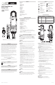
A. Clamp: Measure inductive AC current. Opens to 0.76” (19.10mm).
B. Conductor Alignment Marks: Used to aid the visual alignment of a
conductor when measuring inductive amperage. Greatest accuracy is
achieved when the conductor inside the clamp is centered at the intersection
of these marks.
C. Category Max Indicator: Maximum CAT Rating for Clamp.
D. Hand Guide: Used as a point of reference for the operator’s safety.
E. Clamp Lever: Opens and closes current clamp. Do not allow fingers or
objects to become pinched in the clamp as it closes.
•
CAUTION: When sliding the clamp lever, be careful not to inadvertently
press any button when gripping the meter. That will place the meter in a
mode that was not desired.
F. A-Hold/LRA Inrush Button:
• Auto-Hold: Press to enable Auto-Hold. Press again to return to live readings.
• Captures present value displayed. When a new stable value is detected,
with more than 5% difference than displayed value, the meter displays the
new value.
• Press and hold the A-Hold button when meter is in Auto-Hold mode to
disable Auto power off mode. Press and hold again to enable Auto power
off mode.
• When the meter is in Auto-Hold mode, there will be an audible beep while
the meter captures a new, stable value.
• LRA Inrush: Press and hold to enable LRA Inrush mode. Press and hold to
return to live readings.
• Used for measuring compressor motor start current.
• When powering on the meter using this button, the meter will default to
last mode used when meter was powered off.
G. Ohms/Continuity/Backlight Button:
• Ohms: Press to enter Ohms measurement mode.
• Continuity: Press again to enter Continuity measurement mode.
• AC Amps: Press again to enter AC Amps measurement mode.
• Backlight: Press and hold to turn on backlight. Press and hold again to turn
off backlight.
• Backlight duration is 1 minute.
H. AC/DC Volts/Power Button:
• AC Volts: Press to enter AC Volts measurement mode.
• DC Volts: Press again to enter DC Volts measurement mode.
• AC Amps: Press again to enter AC Amps measurement mode.
• Press and hold to power off meter.
I. Display: High contrast backlit display.
J. Category Max Indicator: Maximum CAT Rating for test lead connections to
meter.
NOTE: Please see Test Lead Notes section of this manual for specific
CAT Rating of the test leads.
K. Test Leads: Permanent test leads.
• Multifunction test lead used for measuring: AC or DC volts, resistance
and continuity.
L. Serial Number
M. Battery Cover: Easy access for replacing batteries.
N. Battery Cover Latches: Convenient, quick opening.
O. Test Lead Holders: For storing test leads when not in use.
S/N:
CATIV
600V
CATIV
600V
OPEN
LOCK
OPEN
LOCK
L
M
N
K
O
CAT IV
600V
V
Ω
DL220
600V CAT IV 200A
E
D
A
C
I
J
B
A-HOLD
LRA INRUSH
F
G
H
600V
CAT IV
CAT IV
600V
V
Ω
DL220
600V CAT IV 200A
CAT IV
600V
CAT IV
600V