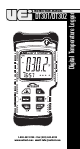
DT301/DT302 1-800-547-5740 • Fax: (503) 643-6322 www.ueitest.com • email: info@ueitest.
TABLE OF CONTENTS Introduction . . . . . . . . . . . . . . . . . . . . . . . . . . . . . . . . . . . . . . . . . .1 Safety . . . . . . . . . . . . . . . . . . . . . . . . . . . . . . . . . . . . . . . . . . . . . .1 Controls and Indicators . . . . . . . . . . . . . . . . . . . . . . . . . . . . . . . .2 Features LCD Display . . . . . . . . . . . . . . . . . . . . . . . . . . . . . . . . . . . . . . . .3 Buttons . . . . . . . . . . . . . . . . . . . . . . . . . . . . . . . . . . . . . . . . . . .
Introduction The DT301 & DT302 Features include • IP67 Water/Dustproof rating • Large Backlit Multi paramater display • Convenient Probe Storage • Accepts J,K,T and E type Thermocouples • Min/Max and Data Hold • 9,999 Memory position Logging with USB software download • Relative (DT301) • Temperature Differential T1-T2 (DT302) Safety Notes These are a few common safety practices for those working around temperature critical environments: • Follow the manufacturer’s maintenance procedures when servicing eq
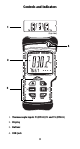
Controls and Indicators 1 (top view) 4 2 3 1. Thermocouple inputs T1(DT301)T1 and T2 (DT302) 2. Display 3. Buttons 4.
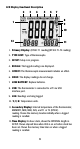
LCD Display Functional Description 2 3 4 5 6 7 8 9 1 10 12 11 1. Primary Display: (DT301: T1 reading)(DT302: T1-T2 reading) 2. TYPE KJET: Type of thermocouple. 3. SETUP: Setup is in progress. 4. RECALL: The logged readings are displayed. 5. OFFSET: The thermocouple measurement includes an offset. 6. HOLD: The display readings do not change. 7. LOW BATTERY: Replace batteries. 8. USB: The thermometer is connected to a PC via USB interface port. 9. LOG: Readings are being logged. 10.
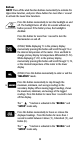
Buttons NOTE: Press all the dual function buttons momentarily to activate the Upper Row Function ,and press these buttons for more than 1 second to activate the Lower Row Functions. Press this button momentarily to turn the backlight on and off. The backlight turns off after 30 seconds without any button pressed. If the battery is low, the backlight is disabled. Press this button for more than 1 second to turn the thermometer on and off.
Press this button momentarily to recall or stop viewing logged readings and MIN/MAX readings. Press this button for more than 1 second to start or exit “SETUP”. The “EXIT” function is activated in the “RECALL” and “SETUP” mode only. Press this button momentarily to start or stop logging. Press this button for more than 1 second to clear logged readings. To clear logged data press and hold until “ “ appears in the lower display. To execute the clear press and hold until “ “ appears.
Setting the Date 1. Entering Setup will show the first option of “ 2. Press “ENTER” and the display will show “ 3. Press “ “ or “ “ “ “ to select the correct year. Press “ENTER” 4. Next the meter will indicate month and day with “ “. Press “ “ or “ “ to select the correct day. Press “ENTER” 5. Press “ “ or “ “ENTER” Setting the Time Units “ to select the correct month. Press 1. While in “SETUP” mode, scroll until the display shows “ “ in the primary display and “ “ in the secondary display. 2.
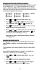
Changing the Auto-Power-Off Time (in minutes) The thermometer enters Auto-Power-Off mode if no button is pressed for 30 minutes. Press “ “ to turn the thermometer on. You can enable or disable Auto-Power-Off mode and also you can select the Auto-Power-Off mode and also you can select the Auto-Power-Off time (in minutes) among the 9 choices below: 1 00:10 h:m 4 00:40 h:m 7 00:70 h:m 1.
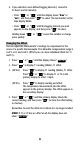
4. If you selected a user-defined logging interval (1 second to 23 hours and 59 minutes). • Press “ “ or “ “ until the display shows “h:m” or “m:s”, and then press “ “ to select. The last number in the time display blinks. • Press “ “ or “ “ until the logging interval you want appears on the display, and then press “ “ to select. Holding down “ more quickly.
Resetting the Thermometer If you want to retore the thermometer settings as delivered from the factory, press “ “ or “ “ until the display shows “ “ then press “ “ to display “ “ in the primary display. Press “ “ to exit setup. 2. How to Measure Temperature Connecting a Thermocouple Thermocouples are color coded by based on the ANSI color code: Type J K Color Black Yellow Type T E Color Blue Purple 1. Plug a thermocouple into the input terminal(s). 2.
Holding the Displayed Temperature 1. Press “ “ momentarily to freeze the readings on the display. The display shows “ HOLD “. 2. Press “ “ momentarily again to turn off the “ HOLD “ function. NOTE: Press “ “ when turning on the thermometer to test the display. All display segments appear. Using the Relative Measurements (DT301) 1. Press “ “ momentarily to enter or exit the “RELATIVE” mode. When the thermometer is in Relative mode, the display shows “REL”. 2.
Using the Offset to Compensate for Probe Errors Use the offset option in “SETUP” to adjust temperature readings to compensate for the errors of a specified thermocouple. 1. Plug the thermocouple into the input terminal. 2. Place the thermocouple in a known stable temperature environment (such as an ice bath or a dry well calibrator). 3. Allow the readings to stabilize. 4. In “SETUP”, change the offset until the primary display reading matches the calibration temperature. See “How to Change Setup Options” 3.
Starting and Stopping Logging Memory clear, and PC communications are in accessible during logging. Recall function is enabled during logging. 1. Set the time and the logging interval, see “How to Change Setup Options”. 2. Press “ “ momentarily to start logging. The display shows “ LOG “. 3. Press “ “ momentarily again to stop logging. Clearing Memory When memory is full, “ “ appears in the secondary display and logging stops. You can clear memory in normal or MIN/MAX mode. 1.
5. Press “ “ momentarily or turn off the thermometer to stop viewing logged readings. NOTE: The thermometer calculates the minimum and maximum of all logging sessions in memory. 4. How to Communicate with a PC The thermometer is equipped with an USB interface port. A Windows® software (WS600) CD and USB interface cable kit is available for data acquisition applications. This kit is required to connect the thermometer to a PC. The thermometer comes with this optional accessory kit.
These guidelines will help you attain long and reliable service from your meter: 1. Calibrate your meter annually to ensure it meets original performance specifications. 2. Keep your meter dry. If it gets wet, wipe it dry immediately. Liquids damage electronic circuits. 3. Whenever practical, keep the meter away from dust and dirt, which can cause premature wear. 4. Although your meter is built to withstand the rigors of daily use, it can be damaged by severe impacts.
Battery Replacement Always use a fresh replacement battery of the specified size and type. Immediately remove the old or weak battery from the meter and dispose of it in accordance with your local disposal regulations. Old or defective batteries can leak chemicals that corrode electronic circuits. WARNING! To avoid electric shock, be sure to turn off the meter’s power and disconnect thermocouples from any equipment before you remove or install batteries.
Specifications Environmental Operating Temperature Storage Temperature Humidity Altitude 14˚ to 122˚F (-10˚ to 50˚C) -40˚ to 140˚F (-40˚ to 60˚C) Non condensing <50˚F (10˚C) 85% RH: 50˚ to 86˚F (10˚ to 30˚C) 70% RH: 86˚ to 104˚F (30˚ to 40˚C) 45% RH: 104˚ to 122˚F (40˚ to 50˚C) Operating - up to 200 m Storage - 10000 m General Dimension Weight Battery Certification Safety CAT I Immersion (30 min) & Dust proof 18.3 (H) x 9.4 (W) x 4.3 (D) cm (7.20” x 3.70” x 1.70) Approx. 460 g (16.
Electrical Measurement range Display Resolution Measurement Accuracy Temperature Coefficient Real Time Clock Tolerance Maximum Differential Common Mode Voltage Temperature Scale J-Type: -346˚ to +2192˚F (-210˚ to +1200˚C) K-Type: -328˚ to +2498˚F (-200˚ to +1370˚C) T-Type: -418˚ to +752˚F (-250˚ to +400˚C) E-Type: -238˚ to +1832˚F (-150˚ to +1000˚C) 0.1˚F/˚C < 1000˚ 1.0˚F/˚C ≥ 1000˚ J, K, T, and E-Type; ±[0.1% +1.0˚F (0.5˚C)] [Below -148˚F (-100˚C): add 0.2% of reading for J, K, and E-Type; and 0.
® DT301/DT302 Digital Temperature Logger Limited Warranty The DT301 and DT302 are warranted to be free from defects in materials and workmanship for a period of five years from the date of purchase. If within the warranty period your instrument should become inoperative from such defects, the unit will be repaired or replaced at UEi’s option.