
User guide

D:S=12:1
6.67@80”
3@36”
2@24”
INF195
Infrared Thermometer
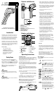
Controls and Indicators
1. Trigger: Initiates measurements.
2. IR Sensor
3. Laser Pointer Beam
4. LCD Display: Temperature
5. LCD Display: Secondary (MIN, MAX, AVG, DIF,
Alarm, Emissivity, Probe)
6. Battery Compartment
7. Thermocouple Socket
Displays and Indicators
Operating Instructions
Taking Measurements
To take a temperature measurement using your INF195, you
simply point the aperture at an object (with or without using
the laser sighting) and pull the trigger. The object’s
temperature will show up on the display and update at a rate
of approximately 2 times per second.
There will be a delay of approximately one-second between
the time you initially pull the trigger and the time the display
comes on. The 60-second auto-hold initiates at the moment
you release the trigger.
NOTE: This thermometer will automatically shut off if left
idle for more than 60 seconds, unless in PRB mode. When in
PRB mode, instrument will shut off if left idle for more than
12 minutes.
Follow these general guidelines to ensure you get the most
accurate readings possible:
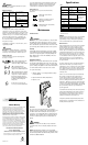
• Besurethemeasuredobjectfillsthe“spot”seenby
the aperture. The distance to spot ratio for the INF195
is 12:1.
This shows the one-foot spot fitting within the one-foot tar-
get area. At this distance, and anything closer, the
target’s temperature will be accurately measured.
NOTE: If the two-foot diameter spot includes unwanted
objects in the background that are not part of the
one-foot square target. The temperature of the
background objects will be figured in with the target’s tem-
perature and throw off your measurement.
•Whencomparingtemperaturesofsimilarobjects
that are far away, take your measurements at the
same distance and angle to the target each time.
•Whenlookingforabnormallyhotorcoldtargetsit
may be acceptable to include background objects
so long as the temperatures in the background
and your methods are consistent.
•Considertheemissivityoftheobjectsyou
are measuring.
•Prepareasurfaceformeasurement.Infrared
thermometers measure only the outer surface of
an object. If emissivity is affecting the
measurement, or you have difficulty putting the
object in the sensors line-of-site, you may need to
prepare a surface that’s easy for the infrared
thermometer to read. A piece of masking tape is a
good target and it will rapidly take on the
temperature of the object it is attached to.
•Beawarethatyoucannotmeasurethe
temperature of air between the Infrared
thermometer and an object. Air vents (registers)
are quick to take on the temperature of outlet air.
However, you must aim directly at the vent if you
are measuring outlet air temperature.
•Keepyourinfraredthermometerawayfrom
strongelectricalfields.Whenworkingneara
strong electrical field, like that under the hood of
yourcar,watchforunusualreadingsoran“over
load”indication.Often,youcanmovethe
thermometer just a few inches to escape the
influence of the interference.
•KeepyourINF195withinitsuseandstorage
temperature range. Excessive heat or cold will
adversely affect the accuracy of your readings.
Whenthetriggerispulledthetarget’s
temperature will be displayed in a near real-time
mode (less than 1/2 second between
measurements). The temperature will remain
on the display for seven seconds after the trigger
is released.
Emissivity
Not all surfaces emit infrared energy at the same
level. A shiny surface will emit much less infrared
energy at a given temperature when compared to
a flat black surface. The INF195 has three preset
emissivity levels used to compensate for variances
in your target.
High (0.95) will work for most common surfaces
and is set as default for many infrared
thermometers. Medium (070) is best for oxidized
copper or rusty iron. Use Low (0.30) for surfaces
that emit less energy such as aluminum or brass.
Mode and Functions
Pressthe“MODE”push-buttonwillscrollthroughthe
following options:
: Emissivity data. (The default emissivity
is 0.95)
: Pressthe“MODE”push-button,thenpress
““or““push-buttonstosetthe
emissivity,thenpressthe“MODE”push-
button again to confirm it. The emissivity
can be changed between 0.30, 0.70 and
0.95.
: Pressthe“MODE”push-buttonforthe
maximum (MAX), minimum (MIN), different
between MAX and MIN (DIF) and average
(AVG) modes. During the measurement,
the special modes reading will be displayed
at the bottom of the display near the
mode icon.
: Pressthe““or““push-buttonsto
changethe“HighAlarm”(HAL) or
“LoAlarm”(LAL), then press the trigger to
confirm it. For example: when the reading
81˚F<LAL81.1˚F,thelow“LoAlarm”icon
will flash and you will hear a beep sound.
: Connectthethermocoupletothe
thermocouple socket and apply the probes
to the target being measured. The
thermometer will display the temperature
automatically without pressing any buttons.
To see the minimum or maximum data
during the probe measurement, please hold
downthe““or““push-buttons.
1-800-547-5740 • Fax: (503) 643-6322
www.ueitest.com • email: info@ueitest.com
INSTRUCTION MANUAL
Introduction
The INF195 is perfect for frequent use in advanced or
specialty application environments, where wide tem-
perature ranges and superior optics are essential for
use on targets at greater distances. This full-featured
IR Thermometer is the most comprehensive and
best-valued Infrared Thermometer on the market.
The INF195’s increased features offer advanced trend
analysis for professionals that require a greater quality
of infrared optics, extended measurement and the ver-
satilityofaK-Typesurfaceorcontactprobeandthree
level emissivity to simplify operation.
Features include:
•–76°~1022°F(-60˚~550˚C)
•12:1DistancetoSpotRatio
•MIN/MAX/Differential,Average
•3emissivitylevels:(0.30,0.70,0.95)
•Hi/lowAlarm(Useradjustable)
•K-Typethermocoupleinput
•CarryCase
Safety Notes
Beforeusingthismeter,readallsafetyinformation
carefully.Inthismanualtheword“WARNING”isusedto
indicate conditions or actions that may pose physical haz-
ards to the user. The word “CAUTION”isusedtoindicate
conditions or actions that may damage this instrument.
NOTE: The INF195 is not recommended for use on
shiny surfaces such as chrome, mirrors or
polished metals.
WARNING!
To avoid thermal shock, the instrument should be
stored at room temperature between 32˚ to 122˚F (0˚
to+50˚C).
WARNING!
DONOTlookdirectlyintothelaserbeam.Permanent
eye damage may result.
1
4
5
2
3
6
7
INF195
1. Mode -button
2. Lock and Backlight
( ) Push-button
3. ˚F/˚C and Laser
( ) Push-button
4. Polarity
5. Main Display
6. Secondary Display
7 F˚ / C˚ Indicator
8. HOLD
9. Battery Life
D:S=12:1
6.67@80”
3@36”
2@24”
INF195
Infrared Thermometer
3
4
1
9
8
6
5
2
6
12