
User Manual


164
The IO interface is made up of a control box interface and an end tool
interface, which can be used to acquire, set, and monitor IO interface
operations. The control box has 8 digital input interfaces, 8 digital
output interfaces, 2 analog input interfaces, and 2 analog output
interfaces. The end tool has 2 digital input interfaces and 2 digital
output interfaces. 2 analog input interfaces. The control box digital IO is
low-level-triggered. The end tool digital IO is high-level-triggered.
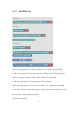
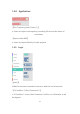
【get I/O 】
● Acquire the I/O interface data of the code block.
【set I/O 】
● Set the I/O interface of the code block, click 【Set】 to run the
command.
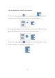
【set I/O when(X, Y, Z, tolerance)】
● When the robotic arm reaches the specified position (the area of the
sphere specified with the trigger position point (X, Y, Z) as the center
(the radius of the sphere is the tolerance radius)), IO is triggered. This
command can be used to trigger IO at a specific location.
X, Y, Z represent the coordinate value of the specified position to be
reached by the robot arm, with the unit of mm.
The digital IO is triggered as soon as the system detects that the TCP