YR903 UHF RFID Evaluation Kit User Manual V1.1 YR903 UHF RFID Evaluation Kit User Manual V1.
YR903 UHF RFID Evaluation Kit User Manual V1.1 Catalogue 1. D-10X View..................................................................................................................................... 3 1-1: Front View .......................................................................................................错误!未定义书签。 1-2: Back View ........................................................................................................错误!未定义书签。 1-3: Plan View ................................
YR903 UHF RFID Evaluation Kit User Manual V1.1 1. YR903 Evaluation Kit View 2. Reader Configurations 2.1 Initial Use 2.1.1 Step 1: Connect The Reader to PC via USB or Serial Port Method NO.1: You can connect the reader to your PC via USB Cable. Next, please switch the DIP to the position as illustrated below: Method NO.
YR903 UHF RFID Evaluation Kit User Manual V1.1 When the indicator light on and sound of a short beep, reader is ready. Note: Driver will be installed automatically when reader is connected to PC for the first time. But some computers may fail. In this case, please install driver manually. (please see: Installing Driver at page 21). 2.1.2 Step 4: Operating Reader via Demo Put the files that named UHFDemo.exe, reader.dll, customControl.dll into a same folder, and doubleclick UHFDemo.exe to run the software.
YR903 UHF RFID Evaluation Kit User Manual V1.1 4. Text communication with the reader: Click on Get in Firmware Version or in Reader Identifier, the following screen displays: Now the reader has been connected to PC successfully. 2.2 Setting RF Parameter After connecting the reader with PC, we need to set some basic RF parameters: RF Output Power & RF Spectrum. Please select RF Setup as illustrated below: 2.2.
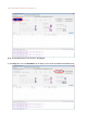
YR903 UHF RFID Evaluation Kit User Manual V1.1 the carrier frequency. Frequency range the reader supports: 865MHz-868MHz(ETSI), 902MHz -928MHz(FCC). You can set the reader in RF Spectrum Setup->User Define, as illustrate below: Users can set RF spectrum via these three parameters: Start Frequency, Frequency Interval, The number of Frequency points. 2.3 ISO-18000-6C tag inventory Connect the Reader correctly. Tag operation could be started when RF Setup is completed.
YR903 UHF RFID Evaluation Kit User Manual V1.1 Inventoried Quantity Speed Total Tag Communication Command Duration Total Inventory Duration ID EPC PC Identification Count Total number of inventory tags since click on Inventory. Speed of identification Tag, unit: piece / sec Total return EPC data of tags (Including repeated data) Time of each inventory command takes, unit: ms Total elapsed time since click on Inventory , unit: ms. The serial number of data. EPC number of tag. Protocol Control word of tag.
YR903 UHF RFID Evaluation Kit User Manual V1.1 Note: the identified tags won’t be shown in the Tag list. 2. Click Stop first, then click Get Buffer.
YR903 UHF RFID Evaluation Kit User Manual V1.1 Functions description under Buffer Mode: Get and Clear: Read the data form cache and then clear the cache. It will be empty when you read the cache again. Query tag Quantity: If you just want to know how many tags are there in cache without details, click on this button. Clear Buffer: Clear the cache and refresh the screen. 2.4 Accessing ISO-18000-6C Tag Click Access Tag, and the screen will display as following: 2.4.
YR903 UHF RFID Evaluation Kit User Manual V1.1 2.4.2 Write Tags The area of Write Tag is the same as Read Tag, but you need to provide access password and information of data to be written. When the operation done successfully, the screen will display as follows: Note: The maximum length of one-time write is 32 Word (64 bytes, 512bits). 2.4.3 Lock Tags A password is necessary to be provided for locking tags.
YR903 UHF RFID Evaluation Kit User Manual V1.1 Same as Write Tags, data of identified tags will be displayed in Tag List. 2.4.4 Kill Tags Password is necessary which can not be 00 00 00 00 before Kill Tags. Therefore, to kill a tag please need change the content of password via Write Tag Operation first. When tag is killed successfully, the information will display as follows: 2.4.5 Tag Selection No matter how many tags in RF region, we just want to access EPC tags which are already identified.
YR903 UHF RFID Evaluation Kit User Manual V1.1 After choosing the tag, please click Select and the screen will display as follows: We could see that the column on the left for Selected Tag has been selected. Next, all the operations are based on the tag with this EPC NO. If you want to cancel the match of EPC, just deselect the column for Selected Tag, as below: 2.4.
YR903 UHF RFID Evaluation Kit User Manual V1.1 ◆ No tags to be operated: Reason why: Tags beyond the area that the RF could cover. For more information about the operation history returned, please defer to the document: UHF RFID Reader Serial Interface Protocol V3.1.
YR903 UHF RFID Evaluation Kit User Manual V1.1 3. Develop your own RFID Application Most functions of the reader can be operated through the demo. But in practical applications, user might need to develop their own applications. Please defer to the document: UHF RFID Reader Serial Interface Protocol V3.1. The reader follows the definition both of the RS - 232 and TCP / IP interface.
YR903 UHF RFID Evaluation Kit User Manual V1.1 4. Installing Driver 1. Open the D-100 Driver folder. 2. Double click on CDM20828_Setup.exe, the following screen displays: 3. Click on Extract: After installation is complete, we could connect reader to PC successfully.
FCC WARNING This device complies with part 15 of the FCC Rules. Operation is subject to the following two conditions: (1) this device may not cause harmful interference, and (2) this device must accept any interference received, including interference that may cause undesired operation. Any changes or modifications not expressly approved by the party responsible for compliance could void the user's authority to operate the equipment.