UIOT/QR4120 "Dimming switch panel" instruction manual Shanghai Unisplendor Lelian Internet of Things Technology Co.
Document revision history date version 2019-10-09 V1.0.
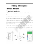
Dimm ming switch pa anel 1 Produuct Fe eaturees 1.11. Functiional descripttion 1. This devvice only supporrts resis stive load and ddimmable LEDD lamps. 2, with loccal control / reemote con ntrol tw wo controol method ds, he client or buttton. youu can conntrol dimming thhrough th 3. When thee light is turneed on, th he brightness off the lig ght t before the lasst time the t willl remainn the state of tthe light ligght was turned t off. o 4.
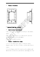
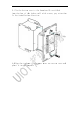
2 Produuct st tructuure 2.1 . Produuct panel diaggram 2.22.
2.3 . Produuct Structure 3 instaallati ion stteps 3.1 . Instaallation requiirements s 1.TThe produuct housing is a special l housing for thhe dimmer r swiitch; 2.TThe instaallation n cassettte is an American UL cerrtified junnction boox with positionn adjustm ment; 3. Cannot be b insta alled outtdoors. 3.2 . Produuct installatiion step ps 1. Cut off the mains powerr supply, , follow w the wirring e to confirm thee wiring is diaagram, coonnect the line, be sure corrrect. 2.
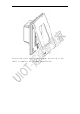
3. Fix the bottom case to the Amer rican UL-certifiied junnction boox of th he indoorr wall with screws, pay attentio on to the insttallatio on directtion. 4.AAlign thee top en nd of thee panel with w the bottom case and d plaace it inn the ba ayonet.
5.PPress thee lower end of tthe panel l to the bottom of the sheell to coomplete the prodduct inst tallation.
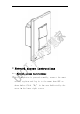
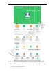
4 Netwoork ac ccess instructions 4.1 . Netwoork access insstructio ons 1. After thhe device e is powwered nor rmally, connect c the smar rt server, register r and log in to the smar rt home AAPP as ick “My” in th he area indicate i e shown beelow: Cli d by the arrow inn the low wer right corner r.
2. Go to thhe interf face showwn below w and cli ick on “ “Device Managemeent” at the red arrow in i the up pper lef t corner r of the interface i e shown below.
3. Go to thhe device e management int terface below b an d click the “+” ” sign in i the red arrow w at the top righht of th he screen to t add th he device.
4. After enntering the t device type selectio on inter face, as s shown inn the fig gure below, find d the “l lighting ” indicateed by the e red arrow in the t figur re beloww and cli ick to proceeed to th he next step.
5. In the "Select " Device D Type" int terface, find th e "LED Dimming Switch Machine" M icon as s shown in i the f igure a click k to go to the next n step p.
6. After cllicking, enter the “Add d LED Dim mming Swwitch Machine” ” interf face below, and follow the t interrface prompts to enter r the neetwork.
you can put the device into the e created d room annd name e operation and a manag gement.
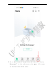
7. After thhe networ rk is successful lly acces ssed, youu can fi ind the roomm you created annd the eq quipment after tthe netw work. Quick opperation of power-on and d power-o off in thhe room.
5 Instrructio ons foor use 5. 1. Instrructions for uuse 1. After thhe device e is connected to t the ne etwork, the control of turni ing on aand off the t light ts and a djusting g e performed on the t APP. the lighht can be 2.
5.11.1.
(1) Device information: view the device name, its own room, and control method (2) Status: Online / Offline (3) Signal strength: show the signal strength of the product (4) Power supply mode: the power supply mode of the product (5) Software version: software version information of the product (6) Hardware version: hardware version information of the product (7) Address: Product Identification Number
5.11.2. Power fa ailure reccovery Thee productt has a memory ffeature, and you can chooose wheether to remember the poower-off state before poower-off. .
If you select memory, you will return to the pre-power-off state when you call again. For example, the power-off recovery function is turned on, and the power is turned on before the power is turned off. After the call is made, the device remains in the state before the power is turned off.
5.11.3. Operatio on recordd On this pagge you can view the hist tory of the deviice being g opeerated.
5.11.4. Backligh ht Cliick on “Backlig “ ght” to set the device backlighht. Such h as: turrn on thee backlight, turrn off th he backlight.
of "turningg on" th he backliight, you u can set the baacklight s. briightness according to yoour needs 6 Produuct pa arametters 6. 1. Produ uct parameterss 1.Product Size:119X74X40. 5 mm 2 . O p e r a t i n g V o l t a ge : A C 1 2 0 V ± 1 0 % 5 0 / 6 0 Hz 3.Operating Temperature: -10℃~40℃ 4 . W o r k i n g H u m i d i t y : < 9 0 % R H ( n o n - c o n d en s i n g ) 5 . C o m m u n i c a t i o n M o d e : I E E E 8 0 2 . 1 5 . 4 ( Z i gb e e ) 6.
7 Commoon pro oblem 8 Precaaution ns 8. 1. Insta allation and uuse prec cautions 1 . T h e r e a r e f r a g i l e d e v i c e s i n t h e p r o d u c t. P l e a s e a v o i d des tructive actions such as dropping and heavy pre ssure. 2 , t h e p r o d u c t i s a p r e c i s i o n e l e c t r o n i c d ev i c e , p a y a t t e n t io n to waterproof and avoid hi gh temperature during u se. 3 . D o n o t d r o p f o re i g n o b j e c t s i n t o t h e m ac h i n e . 4 .
2 . P r o h i b i t p r o d u ct w a t e r : I t m a y c a u s e s ho r t c i r c u i t a n d electric shock. The water o n the panel will affect t he sensitivity of the button. 3 . I t i s f o r b i d d e n to u s e o t h e r A C p o w e r so u r c e s : u s i n g t h e p o w e r s u p p l y b e y on d t h e s p e c i f i c a t i o n s w i ll d a m a g e t h e product or cause harm. 4 .
T h e c o n t e n t r e p r es e n t e d b y t h i s m a r k i s [C l a s s 2 ] . RF eexposure staatement c with h the FCC RF F radiation ex xposure limitts set forth foor an uncontrrolled Thiss equipment complies enviironment. Thiis equipment should be innstalled and operated o with h a minimum distance of 20cm 2 betw ween the radiaator and any part p of your bbody. Thiss equipment meets m the exeemption from m the routine evaluation e lim mits in sectionn 2.5 of RSS-102.