User Instructions
Manuals
Brands
UIOT Manuals
Electronics
Smart switch
1
2
3
4
5
6
7
8
9
10
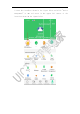
2
enter
t
manageme
n
interfac
e
t
he
inter
f
n
t"
at
t
h
e
shown i
n
f
ace
show
n
h
e
red
a
r
n
the fig
u
n
in
the
r
row
in
t
u
re below.
figure
b
e
t
he
uppe
r
low
and
c
r
left
c
o
c
lick
"de
v
o
rner
of
v
ice
the
1
...
...
7
8
9
10
11
...
...
29