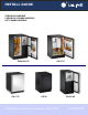
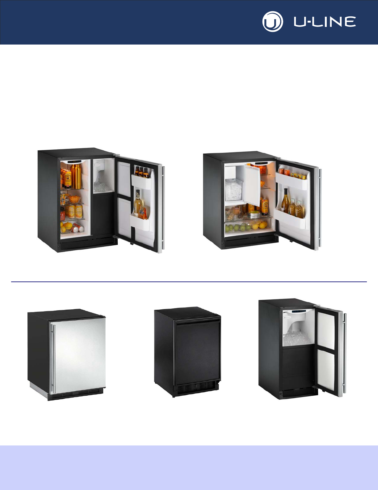
® INSTALL GUIDE CLEAR ICE MODELS CLEAR ICE COMBO MODELS ICE COMBO MODELS CO2175 CLRCO2175 CO1175 CO29 The Built-In Undercounter Leader Since 1962 CLR2160 U-LINE.
1 Table of Contents Safety Precautions Safety Alert Definitions.........................................................................................................................................1 General Precautions ..............................................................................................................................................1 Inspect & Plan Product Registration ..............................................................................................................
2 Safety Precautions General Precautions IMPORTANT • PLEASE READ all instructions before installing, operating, or servicing the appliance. • Proper installation procedures must be followed when completing an installation or relocation of a unit. Consult the installation guide before any installation begins. U-Line contact information appears on the rear cover of this guide.
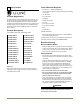
Tools / Material Required 3 Inspect & Plan • Screwdrivers — slotted and Phillips head • 1/4-inch thick door panel material and cutting tools (If installing a 1/4” Panel) • 1/4” Nut Driver Product Registration • 5/16” Nut Driver You have received a carton containing your U-Line Clear Ice, Ice or Ice Combo unit with a package inside containing a Use and Care Guide, a Product Registration Card, and a water line kit. Please complete and mail the Product Registration Card or register online at www.
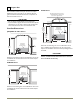
4 Prepare Site Your U-Line product has been designed for either free-standing or built-in installation. When built-in, your unit does not require additional air space for top, sides, or rear. However, the front grille must NOT be obstructed and clearance is required for an electrical connection in the rear. CO29 Series Filler Panel (Not Provided by U-Line) – May Be Added Above or Below Unit to Enclose for a Built-In Look IMPORTANT • Unit can NOT be installed behind a closed cabinet door.
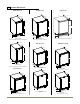
All Models 5 Product Dimensions CLR2160 Series CO1175 Series 23-1/4" * CO29 Series 23” * 23-1/16”* 28-1/2" 34-3/16" 34-3/16" 4-3/4” 3-15/16” 15" 3-13/16” Black and White *Add 3/4” To Depth For Drain Line Clearance 20-13/16" 24" STAINLESS CO1175 *Add 3/16” to Depth For Water Line Clearance *Add 15/16” To Depth For Water Line Clearance CO2175 Series 23-1/4” * CLRCO2175 Series 23-1/16”* 23-1/16”* 34-3/16" 34-3/16” 34-3/16" 3-7/8” 15" 3-13/16” Stainless Steel 24" 3-13/16” *Add 3/4
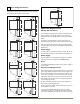
6 Door Swing Dimensions CO29 All units have a zero clearance for the door to open 90°. U-Line recommends a minimum door clearance of 2” to accommodate the handle if the unit is installed next to a wall. 1/4" Min. 21-7/16" Wall CLR2160 Wall 1/4" Min. 2-1/8" Min.
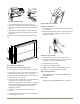
To reverse the door: 7 Standard Doors Remove grille: Door Alignment and Adjustment Remove the grille see MAINTENANCE section of this guide. Align and adjust the door if it is not level, or is not sealing properly. If the door is not sealed the unit may not cool properly, or excessive frost may form in the interior. IMPORTANT Properly aligned, the door’s gasket should be firmly in contact with the cabinet all the way around the door (no gaps).
1 Install bottom hinge: Prepare door for reinstallation: 1. If you have a plate hinge, reorient the pivot screw so it protrudes the opposite direction form the hinge. Remove the pivot screw from the hinge. Turn the plate over and reinstall the screw. For black or white doors: 1. Remove plastic hole plug from top of door handle and reinstall on opposite side. 2. Align hinge outer edge with cabinet. For models with a plate hinge, the flat edge of the hinge alignes with the outer edge of the cabinet. 2.
8 Self-Closing Doors Door Alignment and Adjustment Align and adjust the door if it is not level, or is not sealing properly. If the door is not sealed the unit may not cool properly, or excessive frost may form in the interior. IMPORTANT • Properly aligned, the door’s gasket should be firmly in contact with the cabinet all the way around the door (no gaps). Carefully examine the door’s gasket to ensure that it is firmly in contact with the cabinet.
To reverse the door: Remove existing bottom hinge. Remove the existing bottom hinge (three screws) (2). 3 1 Reinstall hinge to top opposite. Install the hinge just removed from the bottom to the TOP opposite side of the cabinet (three screws) (2). Reinstall Hole Plugs. Install plastic screw plugs (three each, top and bottom) (3) into holes where hinge hardware was removed. 2 Remove door: 1 1. Hold door to keep it from falling. 2. Remove hinge screw pin (1) from top hinge using a Phillips screwdriver.
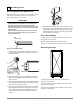
9 Door Panel Installation Custom 1/4'' Thick Door Panel Insert Door Panel Preparation A custom door panel may be inserted into the doorframe. Custom door panels can be flat or raised, as long as the maximum panel thickness, where inserted into the door reveal (channel), is no more than 1/4" thick. For raised panels, the depth of the reveal is 1/4" on all four sides. IMPORTANT Raised panels will reduce the door’s 90° swing/zero clearance if the unit is installed next to a wall or similar type of structure.
CO1175 10 Prepare Power Supply Electrical Specifications WARNING SHOCK HAZARD — Electrical Grounding Required. 24" • Never remove the round grounding prong from the plug and never use a two-prong grounding adapter. 7" • Never use an extension cord to connect power to the unit. 4" CO29 IMPORTANT Electrical installation must observe all state and local codes. This unit requires connection to a grounded (threeprong), polarized receptacle that has been placed by a qualified electrician.
P Drain Connection (CLR2160 CLRCO2175) 11 Prepare Plumbing IMPORTANT CAUTION Plumbing installation must observe all state and local codes. All water and drain connections MUST BE made by a licensed/qualified plumbing contractor. Failure to follow recommendations and instructions may result in damage and/or harm. Water Supply Connection When connecting the water supply, follow these guidelines: • Review the local plumbing codes before you install the unit. • Connect to the cold water supply.
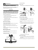
Factory-Installed Drain Pump To check and test hose connections: If your drain line will run up to a stand pipe, disposal or spigot assembly, or does not otherwise meet the requirements for a Gravity Drain, you may have ordered the CLR2160 or CLRCO2175 with a U-Line P60 Drain Pump. See Below for typical installations requiring a Drain Pump. If you need to install a P60 Drain Pump into your unit, see Locally-Installed Drain Pump on Page 14. 1.
Final Water Connection: To connect to drain: 1. Connect the water supply fitting by screwing the brass garden hose fitting to the water valve in the rear of the unit. WARNING To prevent accidental electrocution, make certain that the floor surfaces surrounding the unit are dry whenever power is removed from, or applied to, the unit. 1. Slide 2 hose clamps onto the drain connection on the rear of the appliance. 2. Insert the barbed fitting halfway into this connection. Drain Fitting from Back of Unit 2.
13 Install the Unit 12 Level The Unit Leveling Information Installation It is recommended that the unit is level. 1. Open the water supply valve in the main water source. 1. Use a level to check the levelness of the unit from front to back and from side to side. Level should be placed along top edge and side edge as shown 2. Plug in the power cord. CLR2160 & CLRCO2175 Only • Open the door and press the POWER icon. to turn the unit OFF.
Installation Troubleshooting Q: Problem Water is leaking under the unit. A: Solution A water leak under the unit is most likely caused by a bad connection in the water supply line. Make sure the water line’s brass fitting is screwed tight to its valve and threaded correctly. Q: Problem The door remains open unless it is pushed closed. A: Solution The hinges should be self-closing when the door is open approximately 8".
® INSTALLATION GUIDE SERVICE INFORMATION If you have a problem with this appliance, your use and care guide has troubleshooting information to help you quickly identify common problems and provide information on possible cause and remedy. Answers to Customers Frequently Asked Questions are available at www.u-line.com/customer/faq.cfm. You may contact U-Line directly: GENERAL INQUIRIES: SERVICE ASSISTANCE: U-Line Corporation P.O. Box 245040 Milwaukee, Wisconsin 53224-9540 U.S.A.