-INDEXA. INSTALLATION INSTRUCTIONS 1. TECHNICAL DATA 2 2–4 (a) General Information (b) ER-Series heating Models (or GX, CW, AL, SC) (c) Typical Arrangement of Heater 2. PACKAGING AND SHIPPING 4–5 3. MOUNTING CLEARANCES 5–6 4. PRE-ASSEMBLY 6 5. INSTALLATION 7 6. GAS CONNECTION 8–9 7. ELECTRICAL CONNECTION 10 – 11 8. VENT REQUIREMENT AND DETAILS (a) Unvented units (b) Vertical Vent (c) Horizontal Vent 12 – 13 9. FRESH AIR DUCTED INTAKE (a) Vertical Thru Roof (b) Horizontal Thru Wall 10.
WARNING: Improper installation, adjustment, alteration, service or maintenance can cause property damager, injury, or death. Read the installation, operating, and maintenance instructions thoroughly before installing or servicing this equipment. A. INSTALLATION INSTRUCTIONS A.1 TECHNICAL DATA (a) General Information Model & Heat Input Information all units: Gas Supply Connection: ½-inch NPT Male Electrical Supply: 120V, 1 phase, 60Hz Current Rating: 1.2 AMP MAX (Burner-0.3/Fan – 0.
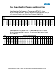
Pipe Capacities For Propane and Natural Gas Pipe Capacities For Propane in Thousands of BTUs Per Hour For pressure drop of 0.5” W.C., based on low-pressure piping based on 6 oz. per sq. in. pressure. Based on one Cubic Foot of Propane = 2500 BTUs. SIZE PIPE INCHES ½ ¾ 1 1¼ 1½ 2 3 4 LENGTH OF STRAIGHT PIPE IN FEET 15 105 425 787.5 1542.5 2425 5040 13545 28035 30 77.5 300 615 1070 1700 3490 9607.5 19687.5 45 65 245 505 882.5 1402.5 2835 7875 16222.5 60 55 212.5 440 770 1212.5 2520 6772.5 14017.
A.2 PACKAGING AND SHIPPING INFORMATION See Appendix ‘A’ for assembly drawings. Materials lists with part numbers and descriptions for each part will accompany each shipment. Heaters include: Burner/Control Radiant Tubes Reflectors Brackets Vacuum Fan U-Bend (U-Tube Units only) Wiring Junction Boxes (Straight Tube Units Only) 2319 Laurelbrook Street, Raleigh, NC 27604 · (800) 542-7221 · FAX (919) 834-4526 · www.ultimate-products.
A.2 PACKAGING AND SHIPPING INFORMATION (CONT.) Options: Fresh air Intake (Mounted to Burner/Control) Fan Vent Adapters- Vertical and Horizontal Thermostat Flexible Gas Connector Ball Valve Vent Hoods Hanging Assembly (chain, etc.) Shipping packages for individual projects will be boxed and crated as outlined on the specific bill of lading. A.3 MOUNTING CLEARANCES The heater should be positioned so that clearances from combustible materials will meet or exceed those shown in the following table.
A.3 MOUNTING CLEARANCES (CONT.) MOUNTING HEIGHT ABOVE FLOOR Mounting Position Horizontal Recommended Minimum Inclined Recommended Minimum 40,000 – 75,000 B.T.U 100,000 – 130,000 B. T. U. 150,000 B. T. U 14 ft 12ft 16ft 14ft 18ft 16ft 11ft 10ft 13ft 12ft 15ft 14ft Ensure that there is adequate provision in the building for combustion and ventilating air supply. Installation must meet minimum requirements of applicable codes.
A.5 INSTALLATION Heater units: At this point raise the tube assembly into position and suspend from previously fixed chains (9 gauge min. galvanized welded link construction), or attach to wall mounting brackets. Wall mounting brackets must support heater at an angle of inclination of 45° ±10°. Longer tube assembly may be raised in more than one sub-assembly with final tube connection made in the air.
A.6 GAS CONNECTION The gas connection on the heater is ½” NPT external thread. SERVICE REQUIREMENTS NAT. GAS L.P. GAS Max. inlet gas supply pressure (in.w.c.) Min. inlet gas supply pressure (in.w.c.) 10.0 6.5 14.0 11.0 Injector sizes and manifold pressure for the burner are shown in the attached table for all heater units. The gas supply piping and connections must be installed so that the minimum pressure stated is achieved.
Air Inlets (Inches/ Millimeters) Model Designation GH/ER/AL/SC GH/ER/AL/SC GH/ER/AL/SC GH/ER/AL/SC GH/ER/l/SC Model Tube Configuration Tube Dia. (In) Burner Intake (in. / M.M.) 12/40,000 S-20 3" S-25 3" S-30 15/150000 18/60,000 22/75,000 29/100,000 GH/ER/AL/SC SC/ER/GX Input KW BTU/HR 38/130,000 44/150,000 Natural Gas Orifice Liquid Petroleum Orifice Fan Inlet (in. / M.M.) Injector Diameter (inches ) Manifold Pressure (in.W.C.) Injector Diameter (inches) Manifold Pressure (in.
A. 7 ELECTRICAL CONNECTION (a) Burner/Control Internal Wiring IMPORTANT: All electrical work should be done by a qualified electrician in accordance with the National Electrical Code ANSI/NFPA 70. Supply: 120 V, 60 Hz, single phase Current Rating: 0.3 amp max 2319 Laurelbrook Street, Raleigh, NC 27604 · (800) 542-7221 · FAX (919) 834-4526 · www.ultimate-products.
A. 7 ELECTRICAL CONNECTION (CONT.) The electrical supply to the heater is by three wires: live, neutral and ground connections. It is recommended that the supply cable be in metallic conduit to the 3/4'” hole provided. Power is ONLY supplied to the terminal in the back of burner as shown below: Power is supplied to fan through the knock out on the side of the burner housing. Fan leads should be connected to the burner leads using the wire nuts provided.
A. 8 VENT REQUIREMENTS AND DETAILS (1) UNVENTED UNITS: Heaters may be installed without a flue providing the governing building codes are met and that consideration is properly given to possibilities of condensation on cold surfaces. Installation shall meet the following requirements when unvented: (A) Internal volume of the heated room must be greater than 214 cu. ft. per 100 BTU/HR of heaters installed.
A. 8 VENT REQUIREMENTS AND DETAILS (CONT.) Flue joints should be sealed using RTV high temperature sealant and secured using at least three (3) sheet metal screws. Should condensation occur flue should be shortened or insulated. The terminal must exit the building at least 7 ft. above any area accessible to the public. The terminal must be at least 3ft. away from any air intake to the building. If the heater is equipped with ducted combustion air, the terminal must be at least 3 ft.
A.10 INSTALLATION CHECK OUT AND START UP Inspect installation and ensure that it has been carried out in accordance with these instructions. Ensure that electrical and gas supplies are isolated. The gas supply should be purged and tested for soundness in accordance with Local and National Safety codes. Open isolating gas valve and test gas connections for soundness using soap solution. Remove burner cover plate by unscrewing 6 screws. Take care not to damage the sealing gasket.
A.10 INSTALLATION CHECK OUT AND START UP (CONT.) To shut down the heater, switch off the power supply to the system. Automatic control of the heater or a series of heaters may be achieved by incorporating thermostats, time switches, manual over-ride switches etc. in the electrical supply to the heater(s). It is essential to allow a delay of 15 seconds after switching off the system before attempting to restart.
B. SERVICE AND MAINTENANCE INSTRUCTIONS B.1 SERVICING INSTRUCTIONS Under normal working conditions, it is recommended that the Ultimate Products Heater should be serviced annually. In exceptionally dirty or dusty conditions such as may occur in a foundry, more frequent servicing may be desirable. Servicing work should be carried out by a qualified gas service engineer. IMPORTANT: 1. Never rest anything, especially ladders, against the heater. 2.
E. BURNER NER/ELECTRODE ASSEMBLY – Inspect the burner/electrode assembly by removing the six screws securing the combustion chamber cover plate to top of control box, taking care not to damage the sealing gasket. Remove the burner head by unscrewing it from the injector taking care not to drop it on the leads of the ignition electrodes. Replace the electrode assembly if it is not in good condition.
B. 3 REPLACEMENT OF COMPONENTS WARNING: TURN OFF GAS AND ELECTRICAL SUPPLIES BEFORE STARTING REPAIR WORK. A. TO REPLACE ANY COMPONENTS IN THE BURNER/CONTROL ASSEMBLY – This assembly should be removed from the heater by disconnecting the gas and electrical supplies (also the fresh air intake duct if used). Loosen the bolts and slide the burner/control assembly from the emitter tube. B. TO REPLACE ELECTRODE ASSEMBLY – Remove top cover of combustion chamber by removing six (6) screws.
F. TO REPLACE THE BURNER/CONTROL UNIT – Remove the control housing cover. After observing their positions, disconnect the wires to the burner control unit. Remove the screws securing the burner control unit to the base of the control housing. Remove the burner control unit. Install replacement unit, observing correct positions for color coded cables. G. TO REPLACE THE VACUUM SWITCH – Remove the burner control unit as in paragraph F. Disconnect the rubber tube connection at the vacuum switch.
USER INSTRUCTIONS ULTIMATE PRODUCTS TUBULAR RADIANT HEATERS Ultimate Products is the distributor of a series of tubular infrared heaters designed for overhead heating of industrial and commercial buildings. Individual heating units are suspended from the roof or mounted at an angle on the wall when inside buildings or horizontal when outside. IMPORTANT 1. This appliance must only be installed by qualified craftsman in accordance with the requirements of local and national codes. 2.
SERVICING To ensure continued efficient and safe operation it is recommended that the heater be serviced regularly by a qualified person, e.g. every year in normal working conditions but in exceptionally dusty or polluted conditions more frequent servicing may be needed. 2319 Laurelbrook Street, Raleigh, NC 27604 · (800) 542-7221 · FAX (919) 834-4526 · www.ultimate-products.
Appendix A 2319 Laurelbrook Street, Raleigh, NC 27604 · (800) 542-7221 · FAX (919) 834-4526 · www.ultimate-products.
2319 Laurelbrook Street, Raleigh, NC 27604 · (800) 542-7221 · FAX (919) 834-4526 · www.ultimate-products.
2319 Laurelbrook Street, Raleigh, NC 27604 · (800) 542-7221 · FAX (919) 834-4526 · www.ultimate-products.
2319 Laurelbrook Street, Raleigh, NC 27604 · (800) 542-7221 · FAX (919) 834-4526 · www.ultimate-products.
LEGEND 0.25 BSSR 1.0 BTL 2BA RSE 0.187 BSSR 0.25 NIFR 5 NIFB WIRE SPECS: ALL ~ 18 A.W.G. UL 1015 WIRE LENGTH TOL: 0.25” INSULATED FEMALE RECEPTACLE 1.0mm2 NON-INSULATED BOOTLACE TERMINAL 2BA RED SHROUDED EYELET 0.187” INSULATED FEMALE RECEPTACLE 0.25” NON- INSULATED FLAG TERMINAL 5mm NON- INSULATED FEMALE BULLET +10 / -0 2319 Laurelbrook Street, Raleigh, NC 27604 · (800) 542-7221 · FAX (919) 834-4526 · www.ultimate-products.
2319 Laurelbrook Street, Raleigh, NC 27604 · (800) 542-7221 · FAX (919) 834-4526 · www.ultimate-products.
2319 Laurelbrook Street, Raleigh, NC 27604 · (800) 542-7221 · FAX (919) 834-4526 · www.ultimate-products.
Wiring Schematic (Part #: S-0500A) 2319 Laurelbrook Street, Raleigh, NC 27604 · (800) 542-7221 · FAX (919) 834-4526 · www.ultimate-products.
2319 Laurelbrook Street, Raleigh, NC 27604 · (800) 542-7221 · FAX (919) 834-4526 · www.ultimate-products.
2319 Laurelbrook Street, Raleigh, NC 27604 · (800) 542-7221 · FAX (919) 834-4526 · www.ultimate-products.
2319 Laurelbrook Street, Raleigh, NC 27604 · (800) 542-7221 · FAX (919) 834-4526 · www.ultimate-products.
2319 Laurelbrook Street, Raleigh, NC 27604 · (800) 542-7221 · FAX (919) 834-4526 · www.ultimate-products.
2319 Laurelbrook Street, Raleigh, NC 27604 · (800) 542-7221 · FAX (919) 834-4526 · www.ultimate-products.
2319 Laurelbrook Street, Raleigh, NC 27604 · (800) 542-7221 · FAX (919) 834-4526 · www.ultimate-products.
2319 Laurelbrook Street, Raleigh, NC 27604 · (800) 542-7221 · FAX (919) 834-4526 · www.ultimate-products.
2319 Laurelbrook Street, Raleigh, NC 27604 · (800) 542-7221 · FAX (919) 834-4526 · www.ultimate-products.
2319 Laurelbrook Street, Raleigh, NC 27604 · (800) 542-7221 · FAX (919) 834-4526 · www.ultimate-products.
2319 Laurelbrook Street, Raleigh, NC 27604 · (800) 542-7221 · FAX (919) 834-4526 · www.ultimate-products.
2319 Laurelbrook Street, Raleigh, NC 27604 · (800) 542-7221 · FAX (919) 834-4526 · www.ultimate-products.
2319 Laurelbrook Street, Raleigh, NC 27604 · (800) 542-7221 · FAX (919) 834-4526 · www.ultimate-products.
2319 Laurelbrook Street, Raleigh, NC 27604 · (800) 542-7221 · FAX (919) 834-4526 · www.ultimate-products.
2319 Laurelbrook Street, Raleigh, NC 27604 · (800) 542-7221 · FAX (919) 834-4526 · www.ultimate-products.
2319 Laurelbrook Street, Raleigh, NC 27604 · (800) 542-7221 · FAX (919) 834-4526 · www.ultimate-products.
2319 Laurelbrook Street, Raleigh, NC 27604 · (800) 542-7221 · FAX (919) 834-4526 · www.ultimate-products.
2319 Laurelbrook Street, Raleigh, NC 27604 · (800) 542-7221 · FAX (919) 834-4526 · www.ultimate-products.
2319 Laurelbrook Street, Raleigh, NC 27604 · (800) 542-7221 · FAX (919) 834-4526 · www.ultimate-products.
2319 Laurelbrook Street, Raleigh, NC 27604 · (800) 542-7221 · FAX (919) 834-4526 · www.ultimate-products.
2319 Laurelbrook Street, Raleigh, NC 27604 · (800) 542-7221 · FAX (919) 834-4526 · www.ultimate-products.
2319 Laurelbrook Street, Raleigh, NC 27604 · (800) 542-7221 · FAX (919) 834-4526 · www.ultimate-products.
2319 Laurelbrook Street, Raleigh, NC 27604 · (800) 542-7221 · FAX (919) 834-4526 · www.ultimate-products.
2319 Laurelbrook Street, Raleigh, NC 27604 · (800) 542-7221 · FAX (919) 834-4526 · www.ultimate-products.
2319 Laurelbrook Street, Raleigh, NC 27604 · (800) 542-7221 · FAX (919) 834-4526 · www.ultimate-products.
APPENDIX ‘B’ 2319 Laurelbrook Street, Raleigh, NC 27604 · (800) 542-7221 · FAX (919) 834-4526 · www.ultimate-products.
2319 Laurelbrook Street, Raleigh, NC 27604 · (800) 542-7221 · FAX (919) 834-4526 · www.ultimate-products.
2319 Laurelbrook Street, Raleigh, NC 27604 · (800) 542-7221 · FAX (919) 834-4526 · www.ultimate-products.
2319 Laurelbrook Street, Raleigh, NC 27604 · (800) 542-7221 · FAX (919) 834-4526 · www.ultimate-products.