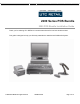
2200 Series POS Bundle 2200 POS Bundle Installation Guide Thank you for selecting UTC RETAIL’s innovative 2200 Series Point of Sale bundle solution! This guide is designed to help you efficiently assemble the 2200 Series POS Bundle System. © 2008 UTC RETAIL. All rights reserved.
200 Series POS Bundle System Installation Guide This guide was prepared by UTC RETAIL to assist personnel with the installation of the bundle components. All attempts have been made to ensure that the information presented in this manual is correct. No liability, expressed or implied, will be assumed by UTC RETAIL or affiliates for damage resulting from the use of this information. All rights reserved.
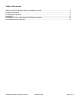
Table of Contents 2200 Series POS Bundle System Installation Guide ................................................................2 Product Information ..................................................................................................................4 Un-boxing the System...............................................................................................................5 Installation..................................................................................................
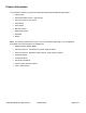
Product Information You will find the following components inside the 2200 Series POS Bundle System Box: • Safety Sheet • 2200 Series POS unit (PC / logic device) • A/C power cord for logic device • LCD Display • Cash drawer • Barcode scanner • POS receipt printer • Keyboard • Mouse Note: The following optional items may or may not be present depending on the configuration purchased and may be shipped in a separate box.
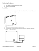
Un-boxing the System 1. Open the point of sale box and remove the contents. 2. Remove all packing materials. Installation 1. Orient the cash drawer on its back side on your cash wrap (counter). Remove the keys. Locate the cash drawer cable package, labeled ‘APG cash drawer 320 Multipro cable kit’. Connect the end with the larger modular plug into the jack on the base of the cash drawer. Figure 1: Bottom View of Drawer 2. Lay down the cash drawer and place the cable to the side. 3.
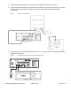
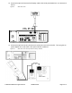
4. Connect the printer USB cable from the printer to a USB port on the rear of the PC. 5. Connect the power cable from the printer power supply to the connector on the printer. Connect the AC cable to the printer power supply and then to a wall outlet or the optional Power Conditioner. Figure 3: 6. Rear View of components Connect the mouse and keyboard cables to the PC. The mouse port on the PC is green and the keyboard port is purple.
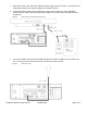
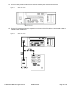
. Remove the LCD, LCD VGA video cable and power supply from the LCD box. Connect the LCD VGA (Video) cable to the Video Port (Blue) on the back of the PC. 8. Connect the power cable from the LCD power supply to the connector on the LCD Display. Connect the AC cable to the LCD power supply and then to a wall outlet or the optional Power Conditioner. Figure 5: 9. Bottom View of LCD and Rear View of PC Connect the USB connector end of the Barcode Scanner cable to a USB port on the back of the PC.
10. Connect the optional MSR (Magnetic Stripe Reader) to a USB Port. For instructions on the MSR bracket installation, refer to the install guide included with the MSR bracket assembly. Figure 7: Rear View of PC and Back View of LCD 11. Connect the optional Payment Terminal (Pin Pad or Signature Capture device) to a Serial Port on the back of the PC. For instructions on the Signature Capture device cable connections, refer to the install guide included with the terminal.
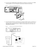
12. Connect the optional Customer Pole Display cable to the serial port labeled Com 4 on the back of the PC. Figure 9: Rear View of PC 13. Connect the optional Inventory Scanner to a serial port on the back of the PC. Then plug the AC power adapter into a wall outlet or the optional Power Conditioner. Figure 10: Rear View of PC and Top View of Inventory Scanner © 2008 UTC RETAIL. All rights reserved.
14. Connect a site provided network cable into the network jack on the back of the PC. Figure 11: Rear View of PC 15. Plug the PC power cord into the receptacle on the rear of the PC and then into the wall outlet or optional Power Conditioner. Figure 12: Rear View of PC © 2008 UTC RETAIL. All rights reserved.
Powering On Your 2200 Series POS Bundle System 1. Remove the plastic protective sheets from the LCD Monitor and the optional customer display. 2. Turn on the ATX PC power by depressing the on/off switch located on the front left-hand side of the PC. 3. To activate the printer, turn on the printer rocker switch located on the front of the printer. 4. To activate the monitor, depress the on/off switch located on the lower right hand side of the monitor bezel.
Troubleshooting Procedures The following table presents symptoms and solutions for problems potentially encountered when installing the 2200 Series Bundled POS System components. Symptom Solutions • • Check to see if the monitor power cable is properly connected to the monitor. Check to see if the SVGA cable is properly connected to the monitor. • Make sure that the LCD monitor power is on. • Check to see if the printer power cable is properly connected to the printer.