SERIES 500 POS KEYBOARD PROGRAMMING & USER’S GUIDE
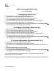
SERIES 500 QUICK REFERENCE GUIDE to KEY PROGRAMMING To Program a Primary Key 1. 2. 3. 4. 5. 6. 7. Swipe Programmer’s Card through Mag Card Reader. Type 00 on the numeric keypad on the Series 500 Keyboard. Press the key on the Series 500 Keyboard that you wish to program. Type the desired key sequence on the AUX (PS/2) keyboard. Press the “ENTER” key next to the numeric keypad on the Series 500 Keyboard. To program additional keys go to Step 3 and repeat process.
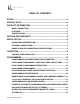
TABLE OF CONTENTS SCOPE ...........................................................................................................vi SPECIAL NOTE.............................................................................................vi PRODUCT INFORMATION ...........................................................................2 MODEL DESCRIPTION ................................................................................................. 2 FEATURES...............................................
MAINTENANCE ............................................................................................58 PRECAUTIONS .............................................................................................................58 CLEANING......................................................................................................................58 KEY LEGEND CHANGE ..............................................................................................
APPENDIX A SERIES 500 POS STANDARD KEYBOARD LAYOUTS A1 APPENDIX B KEYBOARD CABLE/CONNECTOR DATA B1 APPENDIX C ASC11 CHARACTER SET C1 APPENDIX D 101/102-KEY KEYBOARD KEY NUMBER TO SCAN CODE CROSS REFERENCE D1 LIST OF TABLES TABLE 1. SERIES 500 POS KEYBOARD - TYPICAL CONTROLS AND INDICATORS 8 LOCAL MODE PROGRAMMING FUNCTION CODES AND DEFAULT SETTINGS 9 TABLE 3. LOCAL MODE PROGRAMMING INSTRUCTIONS 15 TABLE 4. LOCAL PROGRAMMING COMMANDS FOR KEY MAKE/BREAK AND EXTENDED FUNCTIONS 29 TABLE 5.
FEDERAL COMMUNICATIONS COMMISSION RADIO FREQUENCY INTERFERENCE STATEMENT NOTICE This equipment complies with the limits for a Class A computing device in accordance with the specifications in Part 15 of FCC rules which are designed to minimize radio frequency interference in the installation; however, there is no guarantee that radio or television interference will not occur in any particular installation.
SCOPE This user's guide provides the information and procedures needed to install, operate and program your Series 500 POS Keyboard. Differences in models and optional features are described in this manual, where applicable. It is suggested that the entire manual be read before attempting installation or programming.
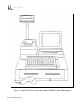
Figure 1.
PRODUCT INFORMATION MODEL DESCRIPTION Series 500 POS Keyboards are point-of-sale (POS) keyboards designed for use with a PC or ASCII terminal. These keyboards have total flexibility in keyboard layout coupled with an extensive programming capability. Each keyboard contains a built-in magnetic stripe reader (MSR), two serial ports, two cash drawer status ports, a main keyboard port, and an auxiliary keyboard port.
OPTIONAL PEDESTAL MOUNT 2
SPECIFICATIONS DIMENSIONS • Depth - 8 Inches • Width - 13 Inches • Height - 3 Inches ENVIRONMENT • Storage temperature -20° to 70°C (-68° to 158°F) • Operating temperature 0° to 50°C (32° to 122°F) APPROVALS • FCC Class A • UL recognized • UL recognized (Canada) WEIGHT • 3.
INSTALLATION UNPACKING AND INSPECTION 1. Examine the exterior of the shipping carton for signs of abuse or damage that may have occurred during transport. Report all evidence of damage or abuse to shipper and dealer. NOTE If any damage may have occurred during transport, examine keyboard and accessories carefully before performing any set-up procedures. Return damaged keyboards to the dealer. See Service paragraph. 2. Open top of shipping carton and carefully remove the keyboard and accessories. 3.
EXTERNAL CONNECTIONS As required by the hardware configuration, connect the keyboard to its host computer and other peripheral devices as shown in Figures 2 and 3. Note that the specific use for each connector on the keyboard is marked adjacent to each connector. Depending on the make and model of the user's equipment, the following cables and/or adapters may need to be supplied by the user to complete the installation: Standard 6-foot cable, 6-Pin Modular to 6-Pin Modular - UTC Part No.
Main RS232 Port Aux RS232 Port Cash Drawer 1 (Driver) Port In Bar Code Scanner CAB20138 Receipt Printer Cash Drawer Port 1 & 2 Cash Drawer 1 (Driver) Port Out Cash Drawer 2 (Drawer) Port In Cash Drawer 1 CAB20138 Cash Drawer 2 (Drawer) Port Out Cash Drawer 2 Drawer Type Jumpers CAB20133 or CAB20137 or CAB20134 PC or Terminal Main KB Port Adapter (optional) Aux KB Port PS2 Type KB 6
Figure 2.
Figure 3.
OPERATION CONTROLS AND INDICATORS Operating controls and indicators on the Series 500 Standard QWERTY Keyboard are shown in Figure 4 and described in Table 1. Because most Series 500 POS Keyboards are customized to match the user's needs, keyboard layouts and the function of the keys may vary widely from the one shown in Figure 4. Although the location of keys may differ among keyboard and types of keyboards, the function of the controls and indicators described in Table 1 pertain to all keyboard types.
Figure 4. Series 500 POS keyboard - typical controls and indicators Table 1. Series 500 POS Keyboard - Typical Controls and Indicators (See Figure 4) Index No. 1 through 3 Name Light Emitting Diode (LED) Indicators Function LED (1) SECURE - When on, indicates keyboard is secured(locked); when off, indicates keyboard is unlocked. LED (2) When on, indicates keyboard is in CAP LOCK mode. LED (3) When on, indicates keyboard is in NUM LOCK mode.
All Other User Defined Keys User defined keys programmed by user/developer.
PROGRAMMING PROGRAMMING KEYBOARD OPERATING PARAMETERS The operating parameters of the keyboard can be configured (programmed) remotely from the host computer or locally at the keyboard. Keyboard programming in the remote mode sets the keyboard parameters as commanded by the host computer input applied at the main communications port. Selection of the local programming mode enables keyboard parameter setup locally at the keyboard.
Table 2. Local Mode Programming Function Codes and Default Settings 11 MSR Channel Separator 1,3 Field ^ (5Eh) for format 1 Used to send a field separator between fields of the magnetic card channel. = (3Dh) for format 3 12 MSR Channel 1,3 Suffix ? (3Fh,0Dh) for both format 1 and 3 Used to send suffixes magnetic card channels. 13 MSR Channel Separator : (3Ah) for format 3 Used to send an account separator on the magnetic card channel.
Table 2. Local Mode Programming Function Codes and Default Settings 24 RS232 Port 0 Word Length User defined Used to change the word length, 7 or 8 bits, of the data at Port 0. 25 RS232 Port 0 Prefix None Used to place a prefix before the packet of data before it is sent out of the keyboard Main Port. (This function is inactive if Port 0 is the main port.) 26 RS232 Port 0 Suffix (0Dh) Used to place a suffix after the packet of data before it is sent out of the keyboard Main Port.
Table 2. Local Mode Programming Function Codes and Default Settings s e c u r e ( l o ck). 41 Keyswitch Position 2 BREAK No output Used to program the BREAK codes of the keyswitch. When the key is turned out of position 2, the switch can send macros and/or perform an internal secure (lock). 42 Keyswitch Position 3 MAKE No output U s e d t o program the MAKE codes of the keyswitch. When the key is turned into position 3, the switch can send macros and/or perform an internal secure (lock).
Table 2. Local Mode Programming Function Codes and Default Settings 71 Enable/Disable Key Clicks On Enables or disables audible key clicks. 0 = off; 1 = on 80 Define Left Shift Key Key 44 See illustration in Appendix D If auxiliary keyboard connected to the Series 500 Keyboard is other than a standard 101 or 102- key keyboard, used to define where the AUX keyboard SHIFT keys are located. Refer to Appendix D.
Table 2. Local Mode Programming Function Codes and Default Settings one keyboard. It is also useful for remote keyboard setup and when making changes in key codes. To download keyboard settings, refer to the procedure given at the rear of the Programming Section in this manual. 99 Exit Program Mode None 17 Used to terminate the programming mode. When activated, causes all programmed changes to be saved and the keyboard to do a warm boot.
LOCAL MODE PROGRAMMING INSTRUCTIONS To program the Series 500 Keyboard in the local mode proceed as follows: 1. Swipe the Programmer's card supplied with the keyboard in the magnetic stripe reader (MSR). For Series 500 Keyboards equipped with the optional 3-position keyswitch adjacent to the LED indicators, set the switch to the AUX position and enter 882 on the keyboard numeric keypad. 2. All LED indicators turn on and the keyboard enunciator beeps three times. 3.
Table 3. Local Mode Programming Instructions - Continued Note: *Default Settings Function Code(s) 00 01 Program Primary Key Functions (00) and Secondary Key Functions (01) Operation Normal Indication Remarks NOTE The keys can be programmed to have primary and secondary levels of function. The primary function is activated when only the designated key is pressed. When programming the secondary operation keys, do not press the Sec Op Key.
Table 3. Local Mode Programming Instructions - Continued Note: *Default Settings Function Code(s) Operation Normal Indication Remarks position keyswitch, move switch out of the AUX position. 02 Copy Primary Key Functions to Secondary Key Positions 1. While in programming mode, at the Series 500 Keyboard numeric keypad, enter Function Code 02. LED (2) turns on. 2. At the Series 500 Keyboard, press the designated key to copy its primary function into the secondary position. 3.
Table 3. Local Mode Programming Instructions - Continued Note: *Default Settings Function Code(s) Operation Normal Indication Remarks Note: Disabling all format tracks will not disable the secure or programming operations. 09 Magnetic Stripe Reader (MSR) Beeper 1. While in programming mode, at the Series 500 Keyboard numeric keypad, enter Function code 09. LED (2) turns on. 2.
Table 3. Local Mode Programming Instructions - Continued Note: *Default Settings Function Code(s) Operation Normal Indication Remarks the Programmer's card. If using the optional 3-position keyswitch, move switch out of the AUX position. 14 15 16 Magnetic Stripe Reader (MSR) Channel 2 Prefix (14) 1. While in programming mode, at the Series 500 Keyboard numeric keypad, enter applicable Function Code 14, 15, or 16. LED (2) flashes. 2.
Table 3. Local Mode Programming Instructions - Continued Note: *Default Settings Function Code(s) Operation Normal Indication Remarks 4. Program the next function code or exit programming mode by entering 99 on Series 500 Keyboard numeric keypad or by swiping the Programmer's card. If using the optional 3-pos ition keyswitch, move switch out of the AUX position. 19 MSR Send 1. While in programming mode, at the Series 500 Keyboard numeric keypad, enter applicable Function Code 19. LED (2) turns on. 2.
Table 3. Local Mode Programming Instructions - Continued Note: *Default Settings Function Code(s) 21 or 31 Main Port 0 (21) AUX Port 1 (31) Stop Bits Operation Normal Indication Remarks 1. While in programming mode, at Series 500 Keyboard numeric keypad, enter Function Code 21 (Port 0) or 31 (Port 1). LED (2) turns on. 2. At Series 500 Keyboard numeric keypad, enter the number of stop bits (1 or 2) per list below. 1 = one stop bit 2 = two stop bits* LED (2) turns off. 3.
Table 3. Local Mode Programming Instructions - Continued Note: *Default Settings Function Code(s) 23 or 33 Main Port 0 (23) AUX Port 1 (33) Handshaking Operation Normal Indication Remarks 1. While in programming mode, at Series 500 Keyboard numeric keypad, enter Function Code 23 (Port 0) or 33 (Port 1). LED (2) turns on. 2. At Series 500 Keyboard numeric keypad, enter the applicable number (0, 1, 2 or 3) to select handshaking per list below. 0 = None 1 = CTS/RTS 2 = XON/XOFF 3 = Both* LED (2) turns off.
Table 3. Local Mode Programming Instructions - Continued Note: *Default Settings Function Code(s) 25 or 35 Comm (RS232) Main Port 0 (25) AUX Port 1 (35) Prefix Operation Normal Indication Remarks 1. While in programming mode, at the Series 500 Keyboard numeric keypad, enter applicable Function Code 25 (Port 0) or 35 (Port 1). LED (2) flashes. 2. At the auxiliary keyboard, press the desired key or type the desired key sequence.
Table 3. Local Mode Programming Instructions - Continued Note: *Default Settings Function Code(s) 39 40 41 42 43 Keyswitch Position 1 MAKE (38) Operation Normal Indication Remarks numeric keypad, enter applicable Function Code 38, 39, 40, 41, 4 2 o r 43 . LED (2) flashes. 2. Keyswitch Position 1 BREAK (39) At the auxiliary keyboard, type the desired MAKE OR BREAK key sequence shown below and /or desired key sequence.
Table 3. Local Mode Programming Instructions - Continued Note: *Default Settings Function Code(s) 45 46 47 48 Drawer 1 Open (45) Closed (46) Operation Normal Indication Remarks 1. While in programming mode, at the Series 500 Keyboard numeric keypad, enter applicable Function Code 45, 46, 47 or 48. LED (2) flashes. 2. At the auxiliary keyboard, press the desired key or type the desired key sequence.
Table 3. Local Mode Programming Instructions - Continued Note: *Default Settings Function Code(s) 70 Indicator LED Mode (70) Operation Normal Indication Remarks 1. While in programming mode, at Series 500 Keyboard numeric keypad, enter Function Code 70. LED (2) turns on. 2. At Series 500 Keyboard numeric keypad, enter the applicable number (0 or 1) to select LED mode of operation. LED Mode 0 = Command mode of operation* 1 = PC mode of operation LED (2) turns off. 3.
Table 3. Local Mode Programming Instructions - Continued Note: *Default Settings Function Code(s) 80 81 Define Position of Left SHIFT Key (80) and Right SHIFT Key (81) Operation Normal Indication Remarks 1. While in programming mode, at the Series 500 Keyboard numeric keypad, enter Function Code 80 or 81. LED (2) flashes. 2. At the auxiliary keyboard, hit the left SHIFT key if programming Function Code 80 or right SHIFT key if programming Function Code 81. 3. At the Series 500 Keyboard, press ENTER.
Table 3. Local Mode Programming Instructions - Continued Note: *Default Settings Function Code(s) Operation Normal Indication Remarks on Series 500 Keyboard numeric keypad or by swiping the Programmer's card. If using the optional 3-position keyswitch, move switch out of the AUX position. 90 Dump System Log This is a command used to read out the Series 500 Keyboard system log data at the main port.
Table 3. Local Mode Programming Instructions - Continued Note: *Default Settings Function Code(s) 97 Default Keyboard Operation Normal Indication Remarks 1. While in programming mode, at Series 500 Keyboard numeric keypad, enter Function Code 97. LED (2) turns on. 2. At Series 500 Keyboard numeric keypad, enter the applicable number (0 or 1) to select mode of default operation per list below. Note selection of 1 below resets the Series 500 Keyboard to all programmed default key and port settings.
Table 4. Local Programming Commands For Key MAKE/BREAK And Extended Functions SERIES 500 KEYBOARD NUMERIC KEYPAD NO. DESCRIPTION 0 Aborts changes to macros. 1 Defines where the output of MAKE codes end and BREAK codes start. Prior to this command, all codes are sent when the keys are pressed (MAKE codes). After command, all codes are sent when keys are released (BREAK codes). 2 Defines where repeating function of keys start.
3. At the Series 500 Keyboard, press the key to be programmed. 4. At the auxiliary keyboard, press and hold the "A" key. 5. At the Series 500 Keyboard numeric keypad, enter 1. 6. At the auxiliary keyboard, release the "A" key. 7. At the Series 500 Keyboard, press ENTER to complete programming of the key. 8. Repeat steps 3 through 7 to program another key. 9. To exit the programming mode, enter 00 99 at the Series 500 Keyboard numeric keypad. EXAMPLE 2.
5. At the Series 500 Keyboard, press ENTER to complete programming of the key. 6. Repeat steps 3 through 5 to program another key. 7. To exit the programming mode, enter 00 99 at the Series 500 Keyboard numeric keypad. EXAMPLE 4. This example erases the macro from the primary and/or secondary key position on the Series 500 Keyboard. 1. Place the Series 500 Keyboard in local programming mode. 2. At the Series 500 Keyboard numeric keypad, enter 00 (for primary keys) or 01 (for secondary keys). 3.
PROGRAMMING IN REMOTE MODE Programming in the remote mode requires the use of a supplemental program that is run on the host computer. If using an IBM PC or compatible computer as the host, use program supplied by Ultimate Technology Corporation when programming the keyboard. To load and use the program, follow the instructions supplied with the program. REMOTE MODE PROGRAMMING MACROS AND COMMAND SUMMARY Refer to Table 5 for details about the commands and MACROS used when programming the keyboard.
NOTE Always apply the COMMIT command (OP Code B4) after programming the keyboard remotely to save the changes in the NVRAM. Failure to use the COMMIT command after making programming changes will result in the loss of the changes the first time power is removed from the keyboard.
Table 5. Remote Programming Mode Commands - Continued OP CODE (HEX) MNEMONIC/DESCRIPTION A0 MACROK COMMAND/ACKNOWLEDGEMENT COMMAND: A0krcCxDx....... Download all key macros for Series 500 Keyboard. Refer to Table 6 for further explanation.
Table 5. Remote Programming Mode Commands - Continued OP CODE (HEX) MNEMONIC/DESCRIPTION A1 MACROP COMMAND/ACKNOWLEDGEMENT COMMAND: A1aCxDx....... Download macros for prefix/suffix.
Table 5. Remote Programming Mode Commands - Continued OP CODE (HEX) MNEMONIC/DESCRIPTION A2 SNDDLY COMMAND/ACKNOWLEDGEMENT COMMAND: A2CxDx Determines rate of delay in milliseconds for sending macros. This command used when interfacing with slow systems.
Table 5. Remote Programming Mode Commands - Continued OP CODE (HEX) MNEMONIC/DESCRIPTION A3 COMMP COMMAND/ACKNOWLEDGEMENT COMMAND: A3Pbbbbbwsph Communications setup for selecting ports, baud rate, word length, stop bits, parity, and method of handshaking.
OP CODE (HEX) MNEMONIC/DESCRIPTION A5 SPCDEF COMMAND/ACKNOWLEDGEMENT COMMAND: A5xCxDx Define where SHIFT, CONTROL, and ALTERNATE keys are located on auxiliary keyboard. A5 x = Op Code = 1 right shift = 2 left shift = 3 right control = 4 left control = 5 right alternate = 6 left alternate Cx = key number (refer to Appendix D) Dx = key number (refer to Appendix D) = terminate command (0D hex) ACKNOWLEDGEMENT: NONE A6 CLICKED COMMAND: A6x Turns keyboard key audible click on A6 or off.
Table 5. Remote Programming Mode Commands - Continued OP CODE (HEX) MNEMONIC/DESCRIPTION A8 NVBDWR COMMAND/ACKNOWLEDGEMENT COMMAND: A8hhhxx..x Write a database register. A8 hhh = Op Code = 3 character address representing the register to write xx = data to write in ASCII or CxDx pairs (16 bytes max.) = terminate command (0D hex) ACKNOWLEDGEMENT: NONE A9 NVBDCLR COMMAND: A9CLR Clear all database registers.
Table 5. Remote Programming Mode Commands - Continued OP CODE (HEX) MNEMONIC/DESCRIPTION AF COMMENT COMMAND/ACKNOWLEDGEMENT COMMAND: AFxxxx-xxxx Use when notes or comments are to be placed in the download file. All data is ignored up to the carriage return . AF = Op Code xx = Comments = terminate command (0D hex) ACKNOWLEDGEMENT: NONE B0 LIGHT COMMAND: B0Lx Provides on/off control for keyboard light emitting diode (LED) indicators. PC mode for NUM and CAP Lock lights is default.
Table 5. Remote Programming Mode Commands - Continued OP CODE (HEX) MNEMONIC/DESCRIPTION B1 BEEPON COMMAND/ACKNOWLEDGEMENT COMMAND: B1pd Controls pitch and duration of beep. If valued for pitch (p) and duration (d) omitted when command activated.
Table 5. Remote Programming Mode Commands - Continued OP CODE (HEX) MNEMONIC/DESCRIPTION B2 SENDP COMMAND/ACKNOWLEDGEMENT COMMAND: B2p........... Sends data to selected port: main serial port, auxiliary serial port, or auxiliary keyboard port.
Table 5. Remote Programming Mode Commands - Continued OP CODE (HEX) MNEMONIC/DESCRIPTION B4 COMMIT COMMAND/ACKNOWLEDGEMENT COMMAND: B4 Writes programming changes to B4 = Op Code the NVRAM. Always apply the = terminate command (0D hex) COMMIT command after programming the keyboard to save ACKNOWLEDGEMENT: NONE the changes in the NVRAM. Failure to use the COMMIT command will result in the loss of the changes the first time power is removed from the keyboard.
Table 5. Remote Programming Mode Commands - Continued OP CODE (HEX) MNEMONIC/DESCRIPTION B8 MSRSND COMMAND/ACKNOWLEDGEMENT COMMAND: B8x Use to send magnetic card reader track data for any one good track or if both tracks are good. B8 x = Op Code A = send any good track B = send if both tracks are good = terminate command (0D hex) ACKNOWLEDGEMENT: NONE B9 CARDED COMMAND: B9c Enables or disables tracks on magnetic card reader.
Table 5. Remote Programming Mode Commands - Continued OP CODE (HEX) MNEMONIC/DESCRIPTION BA BEEPRD COMMAND/ACKNOWLEDGEMENT COMMAND: BAp Selects magnetic card read annunciation mode. BA = Op Code p = annunciation mode select = terminate command (0D hex) Annunciation selection: A = beep on good read B = beep on bad read C = beep on good and bad read D = no beep Annunciation beep frequency for good read is 2000 Hz and for a bad read is 500 Hz.
Table 5. Remote Programming Mode Commands - Continued OP CODE (HEX) MNEMONIC/DESCRIPTION BC CDSTATUS COMMAND/ACKNOWLEDGEMENT COMMAND: BCp Send cash drawer macros for open and closed drawer. BC = Op Code p = selection control = terminate command (0D hex) Selection control: A = cash drawer 1 macros B = cash drawer 2 macros C = cash drawer 1 and 2 macros ACKNOWLEDGEMENT: Send back Macros for request. BD PORTE COMMAND: BDpx Disables all data applied from the selected port.
Table 5. Remote Programming Mode Commands - Continued OP CODE (HEX) MNEMONIC/DESCRIPTION BE VERSION COMMAND/ACKNOWLEDGEMENT COMMAND: BE Sends software version, engineering number, and keyboard type parameters.
PROGRAMMING KEY MAKE/BREAK CODES There are two scan codes assigned to each key, one for when the key is depressed (MAKE code) and the other for when the key is released (BREAK code). Generally, all keys are programmed to output both MAKE and BREAK codes. The SHIFT, CONTROL and ALTERNATE keys are always programmed to output MAKE and BREAK codes so that the system can tell if the key is being held down. Refer to Appendix D for a list of the scan codes associated with the typical 101/102-key keyboard.
EXAMPLES OF REMOTE PROGRAMMING FOR KEY MAKE/BREAK CODE EXAMPLE 1. This example programs a key located at the top left-hand corner of the keyboard (row 1, column A) as a primary key that outputs the scan code for lowercase "z" on MAKE and BREAK. 1. Use the data in Appendix D to find the key code number for the "Z" key on the 101/102keyboard. The "Z" key code number = 46 (decimal). 2. Convert key code 46 (decimal) to its hexadecimal equivalent. The key code = 2E hex. 3.
EXAMPLE 3. This example programs the key at top left-hand corner of keyboard (row 1, column A) as a primary key that outputs the scan code for lowercase "z" on MAKE only. 1. Use the data in Appendix D to find the key code number for the "Z" key on the 101/102keyboard. The "Z" key code number = 46 (decimal). 2. Convert key code 46 (decimal) to its hexadecimal equivalent. The key code = 2E hex. 3.
Parameters same as shown for example 1. EXAMPLE 6. This example programs key at top left-hand corner of keyboard (row 1, column A) as a primary key that outputs the string "abCd" for MAKE. 1. Use the data in Appendix D to find the key code numbers for the A, B, C and D keys on the 101/102-keyboard. The key code numbers for the A, B, C and D keys = 31, 50, 48 and 33, respectively. 2. Convert key codes 31, 50, 48 and 33 to their hexadecimal equivalents. The key codes = 1F, 32, 30 and 21, respectively. 3.
COPYING KEYBOARD SETUP DATA (CLONING) Once a keyboard has been programmed, the parameters can be copied from the source keyboard to other keyboards. This feature saves time and reduces errors when programming more than one keyboard. It is also useful for remote keyboard setup and when making changes in key codes. Downloading of keyboard parameters can be done using one of two methods. The first method is initiated by using the GETSET command (Table 5) issued from the host.
2. At the source keyboard, swipe the Programmer's card in the magnetic stripe reader (MSR). For keyboards equipped with an optional 3-position keyswitch adjacent to the LED indicators, set the switch to the AUX position, then enter 882 at the numeric keypad. 3. All LED indicators turn on and the keyboard enunciator beeps three times. 4. At the source keyboard numeric keypad, enter 98. 5. Exit the local programming mode by typing 99 on the source keyboard numeric keypad or by swiping the Programmer's card.
MAINTENANCE The Series 500 POS Keyboard requires minimal routine maintenance. However, reasonable care of the keyboard will extend its life. The following precautions and routine maintenance actions are recommended. PRECAUTIONS • Do not drop keyboard or allow it to be subjected to impact. • Keep liquids away from keyboard. Thin liquids, such as water, spilled into the keyboard may cause permanent damage. If you spill a thin liquid into the keyboard, disconnect it from the system.
The key legends for full travel keyboards can be changed by one of two methods depending on the type of keys installed on the keyboard. For keys with legends permanently printed on the keys, the entire keycap can be changed by placing a flat head screwdriver under the existing key and applying an upward pressure to aid in pulling off the key top, then push on the new key.
CAUTION Replacement of the battery may result in the need to reprogram the keyboard. For programming instructions, refer to the programming section of this manual. 1. Disconnect keyboard from system. 2. Turn keyboard over to gain access to 5 screws that secure the base of the keyboard case to the top. Remove the 5 screws. 3. Turn keyboard upright.
APPENDIX A SERIES 500 POS STANDARD KEYBOARD LAYOUTS 112 Key 3/4-Inch Standard Layout A1
144 Key Compact 5/8-Inch Size and Flat Panel Membrane Standard Layout A2
Compact 5/8-Inch QWERTY Layout A3
APPENDIX B KEYBOARD CABLE/CONNECTOR DATA BACK CONNECTOR PINOUTS ADAPTER CABLE PINOUTS MAIN RS232 DB9 FEMALE 1 N/C 2 TXD OUT 3 RXD IN 5 GND 6 N/C 7 CTS IN 8 RTS OUT 9 +5 VDC IN/OUT CAB20135 CLONE CABLE DB9 MALE 1 .......................... 2 .......................... 3 .......................... 4 .......................... 5 .....GND........... 6 .......................... 7 .......................... 8 .......................... 9 .....+5VDC......
APPENDIX C ASCII CHARACTER SET 00 01 02 03 04 05 06 07 08 09 0A 0B 0C 0D 0E 0F 10 11 12 13 14 15 16 17 18 19 1A 1B 1C 1D 1E 1F 20 21 22 23 24 25 26 27 28 29 2A 2B 2C 2D 2E 2F Ctrl-@ (NUL) Ctrl-A (SOH) Ctrl-B (STX) Ctrl-C (ETX) Ctrl-D (EOT) Ctrl-E Ctrl-F (ACK) Ctrl-G (BEL) Ctrl-H (BS) Ctrl-I (HT) Ctrl-J (LF) Ctrl-K (VT) Ctrl-L (FF) Ctrl-M (CR) Ctrl-N (SO) Ctrl-O (SI) Ctrl-P Ctrl-Q (DCI) Ctrl-R (DC2) Ctrl-S Ctrl-T (DC4) Ctrl-U (NAK) Ctrl-V (SYN) Ctrl-W (ETB) Ctrl-X (CAN) Ctrl-Y (EM) Ctrl-Z Ctrl-[ (ESC) Ctrl-
APPENDIX D 101/102-KEY KEYBOARD KEY NUMBER TO SCAN CODE CROSS REFERENCE 102-Key Keyboard Key Number Position Layout SCAN CODE KEY NUMBER (Decimal) KEY NUMBER (Hexadecimal) LEGEND SET 1 SET 2 SET 3 1 01 ` 29/A9 0E/F0 0E 0E/F0 0E 2 02 1 02/82 16/F0 16 16/F0 16 3 03 2 03/83 1E/F0 1E 1E/F0 1E 4 04 3 04/84 26/F0 26 26/F0 26 5 05 4 05/85 25/F0 25 25/F0 25 6 06 5 06/86 2E/F0 2E 2E/F0 2E D1
SCAN CODE KEY NUMBER (Decimal) KEY NUMBER (Hexadecimal) LEGEND SET 1 SET 2 SET 3 7 07 6 07/87 36/F0 36 36/F0 36 8 08 7 08/88 3D/F0 3D 3D/F0 3D 9 09 8 09/89 3E/F0 3E 3E/F0 3E 10 0A 9 0A/8A 46/F0 46 46/F0 46 11 0B 0 0B/8B 45/F0 45 45/F0 45 12 0C - 0C/8C 4E/F0 4E 4E/F0 4E 13 0D = 0D/8D 55/F0 55 55/F0 55 15 0F Backspace 0E/8E 66/F0 66 66/F0 66 16 10 Tab 0F/8F 0D/F0 0D 0D/F0 0D 17 11 Q 10/90 15/F0 15 15/F0 15 18 12 W 11/91 1D/F0 1D 1D/F0 1D
SCAN CODE KEY NUMBER (Decimal) KEY NUMBER (Hexadecimal) LEGEND SET 1 SET 2 SET 3 35 23 G 22/A2 34/F0 34 34/F0 34 36 24 H 23/A3 33/F0 33 33/F0 33 37 25 J 24/A4 3B/F0 3B 3B/F0 3B 38 26 K 25/A5 42/F0 42 42/F0 42 39 27 L 26/A6 4B/F0 4B 4B/F0 4B 40 28 ; 27/A7 4C/F0 4C 4C/F0 4C 41 29 ' 28/A8 52/F0 52 52/F0 52 42 2A No Key on 101 keyboard 2B/AB 5D/F0 5D 53/F0 53 43 2B Enter 1C/9C 5A/F0 5A 5A/F0 5A 44 2C Left Shift 2A/AA 12/F0 12 12/F0 12 45 2D No
SCAN CODE KEY NUMBER (Decimal) KEY NUMBER (Hexadecimal) LEGEND SET 1 SET 2 SET 3 61 3D Space bar 39/B9 29/F0 29 29/F0 29 62 3E Right Alternate E0 38/E0 B8 E0 11/E0 F0 11 39/F0 39 64 40 Right Control E0 1D/E0 9D E0 14/E0 F0 14 58/F0 58 75 4B Insert E0 52/E0 D2 E0 70/E0 F0 70 67/F0 67 76 4C Delete E0 53/E0 D3 E0 71/E0 F0 71 64/F0 64 79 4F ç E0 4B/E0 CB E0 6B/E0 F0 6B 61/F0 61 80 50 Home E0 47/E0 C7 E0 6C/E0 F0 6C 6E/F0 6E 81 51 End E0 4F/E0 CF E0 69/E0 F0 69
SCAN CODE KEY NUMBER (Decimal) KEY NUMBER (Hexadecimal) LEGEND SET 1 SET 2 SET 3 Keypad 5 4C/CC 73/F0 73 73/F0 73 ê 50/D0 72/F0 72 72/F0 72 97 61 98 62 99 63 Keypad Insert 52/D2 70/F0 70 70/F0 70 100 64 Keypad * 37/B7 7C/F0 7C 7E/F0 7E 101 65 Keypad PgUp 49/C9 7D/F0 7D 7D/F0 7D 102 66 4D/CD 74/F0 74 74/F0 74 103 67 keypad PgDn 51/D1 7A/F0 7A 7A/F0 7A 104 68 Keypad Delete 53/D3 71/F0 71 71/F0 71 105 69 Keypad - 4A/CA 7B/F0 7B 84/F0 84 106 6A Keypad
SCAN CODE KEY NUMBER (Decimal) KEY NUMBER (Hexadecimal) LEGEND SET 1 SET 2 SET 3 124 7C Print/SysRq E0 2A/E0 37 E0 B7/E0 AA E0 12 E0 7C/E0 F0 7C E0 F0 12 57/F0 57 125 7D Scroll Lock 46/C6 7E/F0 7E 5F/F0 5F 126 7E Pause/Break E1 1D/45 E1/ 9D C5 E1 14 77 E1 F0 14 F0 77 62/F0 62 D6
One Year Limited Service Warranty Terms & Conditions Ultimate Technology Corporation, 100 Rawson Road, Victor, NY 14564, warrants that the product shall be free from defects in material and workmanship for one year from the date of shipment from Ultimate Technology. In accordance with the terms of this limited warranty, Ultimate Technology, at its expense shall either repair or replace any product returned to the Ultimate Technology Service Department in the original container or equivalent.