SERIES 600 POS KEYBOARD PROGRAMMING & USER’S GUIDE
TABLE OF CONTENTS SCOPE ............................................................................................................1 SPECIAL NOTE..............................................................................................1 PRODUCT INFORMATION ...........................................................................3 MODEL DESCRIPTION ................................................................................................. 3 FEATURES...............................................
MAINTENANCE ............................................................................................63 PRECAUTIONS .............................................................................................................63 CLEANING......................................................................................................................63 KEY LEGEND CHANGE ..............................................................................................
APPENDIX APPENDIX A SERIES 600 POS STANDARD KEYBOARD LAYOUTS A1 APPENDIX B KEYBOARD CABLE/CONNECTOR DATA B1 APPENDIX C ASC11 CHARACTER SET C1 APPENDIX D 101/102-KEY KEYBOARD KEY NUMBER TO SCAN CODE CROSS REFERENCE D1 LIST OF TABLES TABLE 1. SERIES 600 POS KEYBOARD - TYPICAL CONTROLS AND INDICATORS 8 TABLE 2. LOCAL MODE PROGRAMMING INSTRUCTIONS 10 TABLE 3.
FEDERAL COMMUNICATIONS COMMISSION RADIO FREQUENCY INTERFERENCE STATEMENT NOTICE This equipment complies with the limits for a Class A computing device in accordance with the specifications in Part 15 of FCC rules which are designed to minimize radio frequency interference in the installation; however, there is no guarantee that radio or television interference will not occur in any particular installation.
SCOPE This user's guide provides the information and procedures needed to install, operate and program your Series 600 POS Keyboard. Differences in models and optional features are described in this manual, where applicable. It is suggested that the entire manual be read before attempting installation or programming.
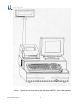
Figure 1.
PRODUCT INFORMATION MODEL DESCRIPTION Series 600 POS Keyboards are point-of-sale (POS) keyboards designed for use with a PC or ASCII terminal or network computer. These keyboards provide total flexibility in keyboard layout as well as extensive programming capability. The Series 600 Keyboard contains two bidirectional serial ports, two status cash drawer ports, main and auxiliary keyboard ports, and a detachable MSR (optional).
BUILT-IN ANNUNCIATOR • Programmable • Selectable tone and duration BUILT-IN DIAGNOSTICS • Self test Series 600 POS Keyboard 4
SPECIFICATIONS DIMENSIONS (d x w x h) • Series 600 only – 7.85” x 14.7” x 2.97” • Series 600 w/MSR – 7.85” x 16.2” x 2.97” ENVIRONMENT • Storage temperature: -40° to 60°C • Operating temperature: 0° to 50°C WEIGHT • Series 600 w/MSR - 3.
INSTALLATION UNPACKING AND INSPECTION 1. Examine the exterior of the shipping carton for signs of abuse or damage that may have occurred during transport. Report all evidence of damage or abuse to shipper and dealer. 2. Open top of shipping carton and carefully remove the keyboard and accessories. 3. Remove shipping retainers and protective covers from the keyboard and accessories. • Series 600 Keyboard NOTE Retain a set of shipping retainers, protective covers, and the shipping carton.
EXTERNAL CONNECTIONS As required by the hardware configuration, connect the keyboard to its host computer and other peripheral devices as shown in Figures 2 and 3. Note that the specific use for each connector on the keyboard is marked adjacent to each connector. Depending on the make and model of the user's equipment, the following cables and/or adapters may need to be supplied by the user to complete the installation: Standard 6-foot cable, 6-Pin Modular to 6-Pin Modular - UTC Part No.
Main RS232 Port Bar Code Scanner or Check Reader Aux RS232 Port Receipt Printer Cash Drawer Port 1 & 2 Cash Drawer 1 (Driver) Port In Cash Drawer 1 (Driver) Port Out Cash Drawer 1 Cash Drawer 2 (Driver) Port In Cash Drawer 2 (Driver) Port Out Cash Drawer 2 Drawer Type Jumpers CAB20133 or CAB20137 or CAB20134 PC or Terminal Main KB Port Adapter (optional) Aux KB Port Series 600 POS Keyboard PS2 Type KB 8
Figure 2.
ITEM Auxiliary Keyboard Main Keyboard Jumpers Drawer 2 Driver 2 Drawer 1 Driver 1 Auxiliary RS232 Main RS232 DESCRIPTION To attach auxiliary keyboard Connection to PC or Terminal Set jumpers to match printer Status from drawer 2 Signal to open drawer 2 Status from drawer 1 Signal to open drawer 1 Serial accessory ports for scanner, MICR, etc. or used as main communication port Serial accessory ports for scanner, MICR, etc. Figure 3.
OPERATION CONTROLS AND INDICATORS Operating controls and indicators on the Series 600 Standard QWERTY Keyboard are shown in Figure 4 and described in Table 1. Because most Series 600 POS Keyboards are customized to match the user's needs, keyboard layouts and the function of the keys may vary from Figure 4. Although the location of keys may differ among types of keyboards, the function of the controls and indicators described in Table 1 pertain to all keyboard types.
Figure 4. Series 600 POS keyboard - Typical Controls and Indicators Table 1. Series 600 POS Keyboard - Typical Controls and Indicators Index No. 1 through 3 Name Light Emitting Diode (LED) Indicators Function LED (1) SECURE - When on, indicates keyboard is secured(locked); when off, indicates keyboard is unlocked. LED (2) When on, indicates keyboard is in CAP LOCK mode. LED (3) When on, indicates keyboard is in NUM LOCK mode.
PROGRAMMING PROGRAMMING KEYBOARD OPERATING PARAMETERS The operating parameters of the keyboard can be configured (programmed) remotely from the host computer or locally at the keyboard. Keyboard programming in the remote mode sets the keyboard parameters as commanded by the host computer input applied at the main communications port. Selection of the local programming mode enables keyboard parameter setup locally at the keyboard.
Table 2. Local Mode Programming Instructions * = Default Settings Function Code(s) Operation Normal Indication Remarks 00 NOTE 01 The keys can be programmed to have primary and secondary levels of function. The primary function is activated when only the designated key is pressed. When programming the secondary operation keys, do not press the Sec Op Key.
Table 2. Local Mode Programming Instructions * = Default Settings Function Code(s) 02 Code Primary Key Functions to Secondary Key Positions Operation 1. Normal Indication Remarks Swipe Program Card. While in programming mode, at the Series 600 Keyboard numeric keypad, enter Function Code 02. LED (2) turns on. 2. At the Series 600 Keyboard, press the designated key to copy its primary function into the secondary position. 3. Repeat 2 for next key to be programmed. 4. When completed, press ENTER.
Table 2. Local Mode Programming Instructions * = Default Settings Function Code(s) 08 Enable/Disable Magnetic Stripe Reader (MSR) Tracks Operation 1. Normal Indication Remarks Swipe Program Card. While in programming mode, at the Series 600 Keyboard numeric keypad, enter Function Code 08. LED (2) turns on. 2. At the Series 600 Keyboard numeric keypad, enter the applicable number (1 through 7) to select the MSR track configuration per list below.
Table 2. Local Mode Programming Instructions * = Default Settings Function Code(s) 10 Operation 1. 11 2. Magnetic Stripe Reader (MSR) Track 1,3 Swipe Program Card. While in programming mode, at the Series 600 Keyboard numeric keypad, enter applicable Function Code 10, 11, 12 or 13. At the auxiliary keyboard, press the desired key or type the desired key sequence. Note that the maximum number of key codes that can be entered is limited to 24 – this is the equivalent to approximately 12 key strokes.
Table 2. Local Mode Programming Instructions * = Default Settings Function Code(s) 17 Operation 1. 18 Magnetic Stripe Reader (MSR) Track 1,3 Bad Read (17) Normal Indication Remarks Swipe Program Card. While in programming mode, at the Series 600 Keyboard numeric keypad, enter applicable Function Code 17, or 18. LED (2) flashes. 2. At the auxiliary keyboard, press the desired key or type the desired key sequence.
Table 2. Local Mode Programming Instructions * = Default Settings Function Code(s) 20 or 30 Comm (RS232) Main Port 0 (20) AUX Port 1 (30) Baud Rate Operation 1. Normal Indication Remarks Swipe Program Card. While in programming mode, at the Series 600 Keyboard numeric keypad, enter Function Code 20 (Port 0) or 30 (Port 1). LED (2) turns on. 2. At Series 600 Keyboard numeric keypad, enter the applicable number (1 through 9) to select baud rate per list below.
Table 2. Local Mode Programming Instructions * = Default Settings Function Code(s) 22 or 32 Main Port 0 (22) AUX Port 1 (32) Parity Operation 1. Normal Indication Remarks Swipe Program Card. While in programming mode, at the Series 600 Keyboard numeric keypad, enter Function Code 22 (Port 0) or 32 (Port 1). LED (2) turns on. 2. At Series 600 Keyboard numeric keypad, enter the applicable number (0, 1 or 2) to select type of parity per list below. 0 = none* 1 = odd 2 = even LED (2) turns off. 3.
Table 2. Local Mode Programming Instructions * = Default Settings Function Code(s) 24 or 34 Main Port 0 (24) AUX Port 1 (34) Word Length Operation 1. Normal Indication Remarks Swipe Program Card. While in programming mode, at the Series 600 Keyboard numeric keypad, enter Function Code 24 (Port 0) or 34 (Port 1). LED (2) turns on. 2. At Series 600 Keyboard numeric keypad, enter the applicable number (7 or 8) to select word length per list below. 7 = 7 data bits 8 = 8 data bits* LED (2) turns off. 3.
Table 2. Local Mode Programming Instructions * = Default Settings Function Code(s) 26 or 36 Comm (RS232) Main Port 0 (26) AUX Port 1 (36) Suffix Operation 1. Normal Indication Remarks Swipe Program Card. While in programming mode, at the Series 600 Keyboard numeric keypad, enter applicable Function Code 26 (Port 0) or 36 (Port 1). LED (2) flashes. 2. At the auxiliary keyboard, press the desired key or type the desired key sequence.
Table 2. Local Mode Programming Instructions * = Default Settings Function Code(s) 38 39 40 41 42 43 Keyswitch Position 1 MAKE (38) Operation 1. Normal Indication Swipe Program Card. While in programming mode, at the Series 600 Keyboard numeric keypad, enter applicable Function Code 38, 39, 40, 21, 42, or 43. LED (2) flashes. 2. At the auxiliary keyboard, type the desired MAKE or BREAK key sequence shown below and/or desired key sequence.
Series 600 POS Keyboard 24
Table 2. Local Mode Programming Instructions * = Default Settings Function Code(s) 45 46 47 48 Drawer 1 Open (45) Closed (46) Operation 1. Normal Indication Remarks Swipe Program Card. While in programming mode, at the Series 600 Keyboard numeric keypad, enter applicable Function Code 45, 46, 47, or 48. LED (2) flashes. 2. At the auxiliary keyboard, type the desired key or type the desired key sequence.
Table 2. Local Mode Programming Instructions * = Default Settings Function Code(s) Operation Normal Indication Remarks 50 Disable Keys The Series 600 Keyboard can be programmed to become disabled while 1 or more cash drawer(s) is open. While Cash 1. Drawer Open Swipe Program Card. While in programming mode, at the Series 600 Keyboard numeric keypad, enter Function Code 50. LED (2) flashes. 2. On the Series 600 keypad, type the desired funciton listed below.
Table 2. Local Mode Programming Instructions * = Default Settings Function Code(s) 71 Enable/Disable Operation 1. Normal Indication Remarks Swipe Program Card. While in programming mode, at the Series 600 Keyboard numeric keypad, enter Function Code 71. LED (2) turns on. Keyboard Key Clicks (71) 2. At Series 600 Keyboard numeric keypad, enter the applicable number (0 or 1) to select key click tone mode of operation. Key Click Mode 0 = off 1 = on* LED (2) turns off.
Table 2. Local Mode Programming Instructions * = Default Settings Function Code(s) 84 85 Define Left Operation 1. Normal Indication Remarks Swipe Program Card. While in programming mode, at the Series 600 Keyboard numeric keypad, enter Function Code 84 or 85. LED (2) flashes. ALTERNATE Key (84) and 2. At the auxiliary keyboard, hit the left ALTERNATE key if programming Function Code 84 or right ALTERNATE key if programming Function Code 85. 3. At the Series 600 Keyboard, press ENTER.
Table 2. Local Mode Programming Instructions * = Default Settings Function Code(s) 96 Set Secure Mode Operation 1. Normal Indication Remarks Swipe Program Card. While in programming mode, at the Series 600 Keyboard numeric keypad, enter Function Code 96. LED (2) turns on. 2. At Series 600 Keyboard numeric keypad, enter the applicable number (0 or 1) to select override secure mode of operation per list below. 0 = not secure 1 = secure LED (2) turns off. 97 Default Keyboard 3.
LOCAL MODE PROGRAMMING KEY MAKE/BREAK CODES AND EXTENDED FUNCTIONS A summary of all keyboard parameters programmable in the local mode, assigned Function Codes and factory default settings is given in Table 3. Table 3.
Table 3.
FUNCTION CODE PARAMETER DEFAULT SETTING (XXh = Hex Code in ASCII) REMARKS 30 RS232 Port 1 Baud Rate 9600 Baud Rate Used to select a baud rate for Port 1. Baud rates available are: 300, 600, 1200, 2400, 4800, 9600, 19200, 38400 and 57600. 31 RS232 Port 1 Stop Bits 2 stop bits Used to select number of stop bits, 1 or 2, used with Port 1. 32 RS232 Port 1 Parity No parity Used to select parity used with Port 1. Selections available are: no parity, odd parity or even parity.
Table 3. Local Mode programming Function Codes and Default Settings FUNCTION CODE PARAMETER DEFAULT SETTING (XXh = Hex Code in ASCII) REMARKS 44 Keyswitch Polling User defined A l l o w s t h e u s e r t o p o l l f o r keyswitch 1,2, or 3 MAKE/BREAK codes. Two options are available: 0 = unsolicited mode in which codes are sent whenever the keyswitch is rotated, or 1 = solicited mode in which codes are sent only when a B7 command is executed.
Table 3. Local Mode programming Function Codes and Default Settings FUNCTION CODE PARAMETER DEFAULT SETTING (XXh = Hex Code in ASCII) REMARKS 82 Define Left Control Key Key 58 See illustration in Appendix D If auxiliary keyboard connected to the Series 600 Keyboard is other than a standard 101 or 102-key keyboard, used to define where the AUX keyboard CONTROL keys are located. Refer to Appendix D. 83 Define Right Control Key Key 64 See illustration in Appendix D Same as Function Code 82 above.
swiping the Programmer's card.
LOCAL MODE PROGRAMMING KEY MAKE/BREAK CODES AND EXTENDED FUNCTIONS There are two scan codes assigned to each key, one for when the key is depressed (MAKE code) and the other for when the key is released (BREAK code). Generally, all keys are programmed to output both MAKE and BREAK codes. The SHIFT, CONTROL and ALTERNATE keys are always programmed to output MAKE and BREAK codes so that the system can tell if the key is being held down.
EXAMPLE 1. This example sequence programs a “shift” key. 1. Place the Series 600 Keyboard in local programming mode by swiping Program Card. 2. At the Series 600 Keyboard numeric keypad, enter 00 or 01. 3. At the Series 600 Keyboard, press the key to be programmed. 4. At the auxiliary keyboard, press and hold the "Shift" key. 5. At the Series 600 Keyboard numeric keypad, enter 1. 6. At the auxiliary keyboard, release the "Shift" key. 7.
EXAMPLE 3 This example programs a Sec Op Key on the Series 600 Keyboard. 1. Place the Series 600 Keyboard in local programming mode by swiping Program Card. 2. At the Series 600 Keyboard numeric keypad, enter 00. 3. At the Series 600 Keyboard, press the key to be programmed. 4. At the Series 600 Keyboard numeric keypad, enter 6 (Sec Op) or 7 (Sec Op Lock). 5. At the Series 600 Keyboard, press ENTER to complete programming of the key. 6. Repeat steps 3 through 5 to program another key. 7.
PROGRAMMING IN REMOTE MODE Programming in the remote mode requires the use of a supplemental program that is run on the host computer. If using an IBM PC or compatible computer as the host, use program supplied by Ultimate Technology Corporation when programming the keyboard. To load and use the program, follow the instructions supplied with the program. REMOTE MODE PROGRAMMING MACROS AND COMMAND SUMMARY Refer to Table 5 for details about the commands and MACROS used when programming the keyboard.
NOTE Always apply the COMMIT command (OP Code B4) after programming the keyboard remotely to save the changes in the NVRAM. Failure to use the COMMIT command after making programming changes will result in the loss of the changes the first time power is removed from the keyboard.
Table 5. Remote Programming Mode Commands OP CODE (HEX) MNEMONIC/DESCRIPTION A0 MACROK Download all key macros for Series 600 Keyboard. COMMAND/ACKNOWLEDGEMENT COMMAND: A0 k Refer to Table 6 for further explanation. r c Cx Dx A0krcCxDx.......
Table 5. Remote Programming Mode Commands OP CODE (HEX) MNEMONIC/DESCRIPTION A1 MACROP Download macros for prefix/suffix. COMMAND/ACKNOWLEDGEMENT COMMAND: A1 a A1aCxDx.......
Table 5. Remote Programming Mode Commands OP CODE (HEX) MNEMONIC/DESCRIPTION A2 SNDDLY Determines rate of delay in milliseconds for sending macros. This command used when interfacing with slow systems.
Table 5. Remote Programming Mode Commands OP CODE (HEX) MNEMONIC/DESCRIPTION A4 NOTES Used to enter up to 40 characters of notes into RAM. Useful for recording keyboard version and date, etc. COMMAND/ACKNOWLEDGEMENT COMMAND: A4 xx A4xxxx-xxxx = Op Code = Note (max of 40 Characters) = terminate command (0D hex) ACKNOWLEDGEMENT: NONE A5 SPCDEF Define where SHIFT, CONTROL, and ALTERNATE keys are located on auxiliary keyboard.
Table 5. Remote Programming Mode Commands OP CODE (HEX) MNEMONIC/DESCRIPTION A7 NVBDRD Read a database register. COMMAND/ACKNOWLEDGEMENT COMMAND: A7 hhh m A7hhhm = Op Code = 3 character address representing the register to read range "000" to "7FF" in ASCII = mode to read in 0 = string mode up to null 1 = raw mode read as CxDx (16 bytes) = terminate command (0D hex) ACKNOWLEDGEMENT: NONE A8 NVBDWR Write a database register. COMMAND: A8 hhh xx A8hhhxx..
Table 5. Remote Programming Mode Commands OP CODE (HEX) MNEMONIC/DESCRIPTION AD RAWED Puts keyboard in row and column mode used for diagnostics. COMMAND/ACKNOWLEDGEMENT COMMAND: AD x ADx = Op Code 0 = user codes 1 = row and column = terminate command (0D hex) ACKNOWLEDGEMENT: NONE AE SECURE Used to lock keyboard from remote location.
Table 5. Remote Programming Mode Commands OP CODE (HEX) MNEMONIC/DESCRIPTION B0 LIGHT Provides on/off control for keyboard light emitting diode (LED) indicators. PC mode for NUM and CAP Lock lights is default. COMMAND/ACKNOWLEDGEMENT COMMAND: B0Lx B0 L x = Op Code = lamp = on/off = terminate command (0D hex) L: 0, 1, 2, 3, P in ASCII, where 0 = all.
Table 5. Remote Programming Mode Commands OP CODE (HEX) MNEMONIC/DESCRIPTION B1 BEEPON Controls pitch and duration of beep. If valued for pitch (p) and duration (d) omitted when command activated.
Table 5. Remote Programming Mode Commands OP CODE (HEX) MNEMONIC/DESCRIPTION B3 RDERROR Sends all error information to main port for output. COMMAND/ACKNOWLEDGEMENT COMMAND: B3 B3 = Op Code = terminate command (0D hex) Sends all error log information contained in the nonvolatile memory (NVRAM) out the main port. ACKNOWLEDGEMENT: NONE B4 COMMIT Writes programming changes to the NVRAM. Always apply the COMMIT command after programming the keyboard to save the changes in the NVRAM.
Table 5. Remote Programming Mode Commands OP CODE (HEX) MNEMONIC/DESCRIPTION B7 KSSTATUS Send keyswitch MAKE/BREAK codes in current keyswitch 1, 2 or 3 position. COMMAND/ACKNOWLEDGEMENT COMMAND: B7 B7 = Op Code = terminate command (0D hex) ACKNOWLEDGEMENT: NONE B8 MSRSND Use to send magnetic card reader track data for any one good track or if both tracks are good.
Table 5. Remote Programming Mode Commands OP CODE (HEX) MNEMONIC/DESCRIPTION BA BEEPRD Selects magnetic card read annunciation mode. COMMAND/ACKNOWLEDGEMENT COMMAND: BA p BAp = Op Code = annunciation mode select = terminate command (0D hex) Annunciation selection: A = beep on good read B = beep on bad read C = beep on good and bad read D = no beep Annunciation beep frequency for good read is 2000 Hz and for a bad read is 500 Hz.
Table 5. Remote Programming Mode Commands OP CODE (HEX) MNEMONIC/DESCRIPTION BC CDSTATUS Send cash drawer macros for open and closed drawer. COMMAND/ACKNOWLEDGEMENT COMMAND: BC p BCp = Op Code = selection control = terminate command (0D hex) Selection control: A = cash drawer 1 macros B = cash drawer 2 macros C = cash drawer 1 and 2 macros ACKNOWLEDGEMENT: Send back Macros for request. BD PORTE Disables all data applied from the selected port.
Table 5. Remote Programming Mode Commands OP CODE (HEX) MNEMONIC/DESCRIPTION BE VERSION Sends software version, engineering number, and keyboard type parameters. COMMAND/ACKNOWLEDGEMENT COMMAND: BE BE = Op Code = terminate command (0D hex) ACKNOWLEDGEMENT: BEnnnnnvvvvkkkkx-x BE nnnnn vvvv kkkk x-x BF GETSET Sends each key macro, all keyboard communication parameters. Keeps sending until all data has been transferred. Structure of data is in load command format (MACROK).
REMOTE PROGRAMMING KEY MAKE/BREAK CODES There are two scan codes assigned to each key, one for when the key is depressed (MAKE code) and the other for when the key is released (BREAK code). Generally, all keys are programmed to output both MAKE and BREAK codes. The SHIFT, CONTROL and ALTERNATE keys are always programmed to output MAKE and BREAK codes so that the system can tell if the key is being held down. Refer to Appendix D for a list of the scan codes associated with the typical 101/102-key keyboard.
EXAMPLES OF REMOTE PROGRAMMING FOR KEY MAKE/BREAK CODE EXAMPLE 1. This example programs a key located at the top left-hand corner of the keyboard (row 1, column A) as a primary key that outputs the scan code for lowercase "z" on MAKE and BREAK. 1. Use the data in Appendix D to find the key code number for the "Z" key on the 101/102keyboard. The "Z" key code number = 46 (decimal). 2. Convert key code 46 (decimal) to its hexadecimal equivalent. The key code = 2E hex. 3.
EXAMPLE 3. This example programs the key at top left-hand corner of keyboard (row 1, column A) as a primary key that outputs the scan code for lowercase "z" on MAKE only. 1. Use the data in Appendix D to find the key code number for the "Z" key on the 101/102keyboard. The "Z" key code number = 46 (decimal). 2. Convert key code 46 (decimal) to its hexadecimal equivalent. The key code = 2E hex. 3.
EXAMPLE 6. This example programs key at top left-hand corner of keyboard (row 1, column A) as a primary key that outputs the string "abCd" for MAKE. 1. Use the data in Appendix D to find the key code numbers for the A, B, C and D keys on the 101/102-keyboard. The key code numbers for the A, B, C and D keys = 31, 50, 48 and 33, respectively. 2. Convert key codes 31, 50, 48 and 33 to their hexadecimal equivalents. The key codes = 1F, 32, 30 and 21, respectively. 3.
OPOS PROGRAMMING The OPOS keys are defined in Table 7 below. All OPOS keys have the prefix of E0h/48h added to them. Example for OPOS key #32: The output in scan set 2 is E0 48 33 F0 33. All data is sent on the make of the key. Note: See Appendix D for keyboard key number format and scan code cross reference. OPOS Key No. 01 04 07 10 13 16 19 22 25 28 31 34 37 40 43 46 49 Table 7 OPOS Key Definitions Output OPOS Output OPOS Key No. Key No.
MSR PROGRAMMING FOR UTC OPOS DRIVERS The MSR is programmed by using a special prefix. This prefix allows the OPOS driver to determine where the data is coming from. An example of the data stream is shown below. If a track is missing from the magnetic stripe card, the prefix and suffix for that track will still be sent. MSR Track 1 14/F0/14/F0/14c10……..data……..? MSR Track 2 c20……….data…..……..? Function Code (s) Table 8 MSR Programming for UTC OPOS Drivers Operation 1. Track 1 2. 10 (prefix) 3. 4. 1.
Function Code (s) Table 8 MSR Programming for UTC OPOS Drivers Operation 1. Track 2 16 (suffix) 2. 3. 1. Track 2 18 (bad read) 2. 3. 1. MSR 2. 08 (track options) 3. 4. Series 600 POS Keyboard Swipe Program Card. While in programming mode, at the Series 600 Keyboard, enter Function Code 16 (suffix). At the auxiliary keyboard, type ?. At the Series 600 Keyboard, press ENTER. Swipe program Card. While in programming mode, at the Series 600 keyboard, enter Function Code 18 (bad read).
COPYING KEYBOARD SETUP DATA (CLONING) Once a keyboard has been programmed, the parameters can be copied from the source keyboard to other keyboards. This feature saves time and reduces errors when programming more than one keyboard. It is also useful for remote keyboard setup and when making changes in key codes. Downloading of keyboard parameters can be done using one of two methods. The first method is initiated by using the GETSET command (Table 5) issued from the host.
2. At the source keyboard, swipe the Program Card in the magnetic stripe reader (MSR). For keyboards equipped with an optional keyswitch adjacent to the LED indicators, set the switch to the AUX position, then enter 882 at the numeric keypad. 3. All LED indicators turn on and the keyboard enunciator beeps three times. 4. At the source keyboard numeric keypad, enter 98. 5. Exit the local programming mode by typing 99 on the source keyboard numeric keypad or by swiping the Program card.
MAINTENANCE The Series 600 POS Keyboard requires minimal routine maintenance. However, reasonable care of the keyboard will extend its life. The following precautions and routine maintenance actions are recommended. PRECAUTIONS • Do not drop keyboard or allow it to be subjected to impact. • Keep liquids away from keyboard. Thin liquids, such as water, spilled into the keyboard may cause permanent damage. If you spill a thin liquid into the keyboard, disconnect it from the system.
KEY LEGEND CHANGE 3/4 INCH FULL TRAVEL KEYBOARDS The key legends for full travel keyboards can be changed by one of two methods depending on the type of keys installed on the keyboard. For keys with legends permanently printed on the keys, the entire keycap can be changed by placing a flat head screwdriver under the existing key and applying an upward pressure to aid in pulling off the key top, then push on the new key.
1. Disconnect keyboard from system. 2. Turn keyboard over to gain access to 7 screws that secure the base of the keyboard case to the top. Remove the 7 screws. 3. Turn keyboard upright. Gain access to the battery by lifting the top portion of the keyboard assembly from the base and placing it and the attached extended cable/connectors in front of the base. CAUTION Replacement of the battery may result in the need to reprogram the keyboard.
APPENDIX A SERIES 600 POS STANDARD KEYBOARD LAYOUTS QWERTY #1 Default Layout QWERTY #2 Default Layout Series 600 POS Keyboard A1
APPENDIX A SERIES 600 POS STANDARD KEYBOARD LAYOUTS Full Matrix Default Layout Series 600 POS Keyboard A2
APPENDIX B KEYBOARD CABLE/CONNECTOR DATA BACK CONNECTOR PINOUTS MAIN RS232 DB9 FEMALE 1 N/C 2 TXD OUT 3 RXD IN 4 N/C 5 GRD 6 N/C 7 CTS IN 8 RTS OUT 9 +5 VDC IN/OUT AUX RS232 DB9 MALE 1 N/C 2 RXD IN 3 TXD OUT 4 N/C 5 GND 6 N/C 7 RTS OUT 8 CTS IN 9 +5 VDC IN/OUT KEYBOARD MAIN 1 DATA 2 N/C 3 GND 4 +5 VDC IN/OUT 5 CLOCK 6 N/C KEYBOARD AUX 1 DATA 2 N/C 3 GND 4 +5 VDC IN/OUT 5 CLOCK 6 N/C Series 600 POS Keyboard B1
APPENDIX C ASCII CHARACTER SET 00 01 02 03 04 05 06 07 08 09 0A 0B 0C 0D 0E 0F 10 11 12 13 14 15 16 17 18 19 1A 1B 1C 1D 1E 1F 20 21 22 23 24 25 26 27 28 29 2A 2B 2C 2D 2E 2F Ctrl-@ (NUL) Ctrl-A (SOH) Ctrl-B (STX) Ctrl-C (ETX) Ctrl-D (EOT) Ctrl-E Ctrl-F (ACK) Ctrl-G (BEL) Ctrl-H (BS) Ctrl-I (HT) Ctrl-J (LF) Ctrl-K (VT) Ctrl-L (FF) Ctrl-M (CR) Ctrl-N (SO) Ctrl-O (SI) Ctrl-P Ctrl-Q (DCI) Ctrl-R (DC2) Ctrl-S Ctrl-T (DC4) Ctrl-U (NAK) Ctrl-V (SYN) Ctrl-W (ETB) Ctrl-X (CAN) Ctrl-Y (EM) Ctrl-Z Ctrl-[ (ESC) Ctrl-
APPENDIX D 101/102-KEY KEYBOARD KEY NUMBER TO SCAN CODE CROSS REFERENCE 102-Key Keyboard Key Number Position Layout SCAN CODE KEY NUMBER (Decimal) KEY NUMBER (Hexadecimal) LEGEND SET 1 SET 2 SET 3 1 01 ` 29/A9 0E/F0 0E 0E/F0 0E 2 02 1 02/82 16/F0 16 16/F0 16 3 03 2 03/83 1E/F0 1E 1E/F0 1E 4 04 3 04/84 26/F0 26 26/F0 26 5 05 4 05/85 25/F0 25 25/F0 25 6 06 5 06/86 2E/F0 2E 2E/F0 2E 7 07 6 07/87 36/F0 36 36/F0 36 8 08 7 08/88 3D/F0 3D 3D/F0 3D 9 09 8 09
SCAN CODE KEY NUMBER (Decimal) KEY NUMBER (Hexadecimal) LEGEND SET 1 SET 2 SET 3 13 0D = 0D/8D 55/F0 55 55/F0 55 15 0F Backspace 0E/8E 66/F0 66 66/F0 66 16 10 Tab 0F/8F 0D/F0 0D 0D/F0 0D 17 11 Q 10/90 15/F0 15 15/F0 15 18 12 W 11/91 1D/F0 1D 1D/F0 1D 19 13 E 12/92 24/F0 24 24/F0 24 20 14 R 13/93 2D/F0 2D 2D/F0 2D 21 15 T 14/94 2C/F0 2C 2C/F0 2C 22 16 Y 15/95 35/F0 35 35/F0 35 23 17 U 16/96 3C/F0 3C 3C/F0 3C 24 18 I 17/97 43/F0 43 43/F0 4
SCAN CODE KEY NUMBER (Decimal) KEY NUMBER (Hexadecimal) LEGEND SET 1 SET 2 SET 3 35 23 G 22/A2 34/F0 34 34/F0 34 36 24 H 23/A3 33/F0 33 33/F0 33 37 25 J 24/A4 3B/F0 3B 3B/F0 3B 38 26 K 25/A5 42/F0 42 42/F0 42 39 27 L 26/A6 4B/F0 4B 4B/F0 4B 40 28 ; 27/A7 4C/F0 4C 4C/F0 4C 41 29 ' 28/A8 52/F0 52 52/F0 52 42 2A No Key on 101 keyboard 2B/AB 5D/F0 5D 53/F0 53 43 2B Enter 1C/9C 5A/F0 5A 5A/F0 5A 44 2C Left Shift 2A/AA 12/F0 12 12/F0 12 45 2D No
SCAN CODE KEY NUMBER (Decimal) KEY NUMBER (Hexadecimal) LEGEND SET 1 SET 2 SET 3 60 3C Left Alternate 38/B8 11/F0 11 19/F0 19 61 3D Space bar 39/B9 29/F0 29 29/F0 29 62 3E Right Alternate E0 38/E0 B8 E0 11/E0 F0 11 39/F0 39 64 40 Right Control E0 1D/E0 9D E0 14/E0 F0 14 58/F0 58 75 4B Insert E0 52/E0 D2 E0 70/E0 F0 70 67/F0 67 76 4C Delete E0 53/E0 D3 E0 71/E0 F0 71 64/F0 64 79 4F ¬ E0 4B/E0 CB E0 6B/E0 F0 6B 61/F0 61 80 50 Home E0 47/E0 C7 E0 6C/E0 F0 6C
SCAN CODE KEY NUMBER (Decimal) KEY NUMBER (Hexadecimal) LEGEND SET 1 SET 2 SET 3 96 60 Keypad - 48/C8 75/F0 75 75/F0 75 97 61 Keypad 5 4C/CC 73/F0 73 73/F0 73 98 62 Keypad ¯ 50/D0 72/F0 72 72/F0 72 99 63 Keypad Insert 52/D2 70/F0 70 70/F0 70 100 64 Keypad * 37/B7 7C/F0 7C 7E/F0 7E 101 65 Keypad PgUp 49/C9 7D/F0 7D 7D/F0 7D 102 66 4D/CD 74/F0 74 74/F0 74 103 67 keypad PgDn 51/D1 7A/F0 7A 7A/F0 7A 104 68 Keypad Delete 53/D3 71/F0 71 71/F0 71 105 69
SCAN CODE KEY NUMBER (Decimal) KEY NUMBER (Hexadecimal) LEGEND SET 1 SET 2 SET 3 124 7C Print/SysRq E0 2A/E0 37 E0 B7/E0 AA E0 12 E0 7C/E0 F0 7C E0 F0 12 57/F0 57 125 7D Scroll Lock 46/C6 7E/F0 7E 5F/F0 5F 126 7E Pause/Break E1 1D/45 E1/ 9D C5 E1 14 77 E1 F0 14 F0 77 62/F0 62 Series 600 POS Keyboard D6
ULTIMATE TECHNOLOGY CORPORATION 100 Rawson Road VICTOR, NEW YORK 14564 Printed in U.S.A.