Thank you for purchasing our product. Please read this User’s Manual before using the product.
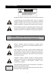
1. Safety Precautions CAUTION RISK OF ELECTRICAL SHOCK. DO NOT OPEN ! CAUTION: TO REDUCE THE RISK OF ELECTRICAL SHOCK, DO NOT REMOVE COVER (OR BACK), NO USER SERVICEABLE PARTS REFER SERVICING TO QUALIFIED SERVICE PERSONNEL. This label may appear on the bottom of the unit due to space limitations.
2. About this document Before installing stand alone DVR, be sure to thoroughly review and follow the instructions in this Users Manual. Pay particular attention to the parts that are marked NOTICE. Also, when connecting with external application, first turn the power OFF and follow manual instruction for appropriate installation. 3. Before reading this document 1. This document is intended for both the administrator and users of stand alone DVR Model. 2.
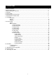
5. Content Table 1. Safety Precautions…………………………………………….………………………….……………………. 2 2. About this document……………………………………………………………………………………………. 3 3. Before reading this document…………………………………………………………………………………. 3 4. Hardware ……………………………………………………………………………………………………….. 3 5. Content Table…………………….……….…………………………………………………………………….. 5 6. Unit Description of Front Panel……………………………………………………………………………….. 5 7. Unit Description of Rear Panel………………………………………………………………………………... 6 8. Installation……………………..
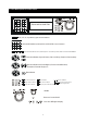
6. Unit Description of Front Panel Removable Hard Disk ESC 16 / 13 / 9 / 4 quarterly split screen button 1/2/3/4/5/6/7/8/9/10/11/12/13/14/15/16 full screen button Picture freeze / Picture zoom in / Auto sequence / Picture in picture / Select channel mode BUTTON Direction Button Up and Down / Record Stop, Playback Pause/step.
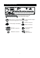
7. Unit Description of Rear Panel 16 Channel Video Input and main/call monitor output Y/C video monitor output Audio Input.
8. Installation Procedure 1) Camera Connection DC LEVEL Connect the camera to the CAMERA INPUT V.P CH1 CH2 CH3 VIDEO CH4 DC MONITOR on the Rear Panel of the 16 CH DVR. CH1 CH2 CH3 CH4 VIDEO LENS AC24V/DC12 Rear part of CAMERA 2) Monitor Connection (Composite Connection Method) Connect the monitor to the MONITOR OUT on CH1 CH2 CH3 CH4 CH1 CH2 CH3 CH4 MONITOR the Rear Panel of the 16 CH DVR.
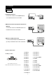
NOTICE: Sensor input is RECOGNIZED as LOW when alarm signal is on a level with GND, and it is recognized as HIGH when alarm signal is FLOATING or 5V. Following is internal circuit. 5 V Internal Circuit D1 Thus, there is a danger of damage, when the sensor input goes to a Negative level or voltage higher than 5V. 5) Network Connection DVR connects to LAN ETHERNET rks TERATRAY CONNECTION ◆To view video image on the computer through internet with DVR view software.
7) Power Connection Connect the power to the POWER CONNECTION on the Rear Panel of the system, and turn on the switch. 4 5 2 3 1 6 8) Turn on the POWER. Make sure the adaptor is 12V/5A. 9) Detail setup in SYSTEM SETUP For detail setup, refer to the instruction of SYSTEM SETUP. 9 1. 2. 3. 4. +12VDC +12VDC +12VDC RTN 5. RTN 6.
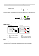
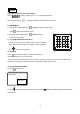
Picture Full screen or quarterly split screen display Press button, to display 16 / 13 / 9 / 4 quarterly split screen. Press numeric buttons to display the desired camera image in full screen. 1.) FREZZE Mode 1. In live and the quad mode press Press (FREEZE) button to freeze image. again to cancel freeze mode. 2. On the full screen display, press (FREEZE) button to freeze full screen image. 2.) Zoom Mode(Display Enlargement.
5.) SEL (Select) >On the 13 / 9 / 4 split screen, press SEL can change the each channel order. 6.) - Press SEL button to active the selection function. - Turn - Press - Press SEL button again to cancel the selection function. the inner-shuttle or button to select the desired camera channel in split-1. change button to change the split-screen position. Alarm Sensor Recording >See the alarm recording setup page 7.) Scheduled Recording >See the scheduled recording setup page 8.
Playback 1. Playback Mode 1) Press PLAY button to begin playback. (System will playback the images in backward) 2. T-SRH button PLAY SETUP PAGE 1) T-SRH: Playback by time search. Press T-SRH button to active playback function. EVENT LIST TIME LIST Press direction button PLAY END: RECYCLE UP/DOWN to choose items.
3) TIME LIST (Playback image by Time-Search): Recorded images list (by hours) TIME SEARCH LIST PAGE : CURSOR, : PAGE, ENTER: PLAY No items or page display limit. Items. DVR recording mode is continued. Press direction button UP/DOWN to choose items. Press values change button to change to next page.
9. FUNCTION SETUP LOGIN 1) Press MENU button to enter into menu. You could do the system function setup in MENU. 2) Password enter window pop-up: LOGIN DVR SYSTEM PASSWORD xxxxx 1. Password (Account-Admin) : 44444 2. Password (Account-User) : 11111 3) Press numeric button to choose password then menu pop-up. 4) Remote controller function buttons are same as DVR panel function buttons.
Basic Operation Press MENU button to enter MAIN SETUP PAGE. MAIN SETUP PAGE 1. HDD INFORMATION 2. DATE-TIME SETUP 3. DISPLAY SETUP 4. CAMERA SETUP 5. BUZZER SETUP 6. AUDIO SETUP 7. SYSTEM SETUP 8. ADVANCED SETUP MENU, ESC: EXIT, ENTER: RUN 1) Use direction button up/down 2) Press button to select setup item. button to enter into sub-menu function setup. 3) Press sub-menu item with direction button up/down or left/right button.
1. HDD INFORMATION NO. SIZE USED BRAND POS 01 xxxxxxxxxxxxxxxxxxxxxxxxxxxxxx MAIN SETUP PAGE 02 xxxxxxxxxxxxxxxxxxxxxxxxxxxxxx 1. HDD INFORMATION 03 xxxxxxxxxxxxxxxxxxxxxxxxxxxxxx 2. DATE-TIME SETUP 04 xxxxxxxxxxxxxxxxxxxxxxxxxxxxxx 3. DISPLAY SETUP 05 xxxxxxxxxxxxxxxxxxxxxxxxxxxxxx 4. CAMERA SETUP STATUS: PARTIAL 5. BUZZER SETUP FRAME: 6. AUDIO SETUP START: 7. SYSTEM SETUP END: 8.
2. DATE-TIME SETUP MAIN SETUP PAGE DATE-TIME SETUP PAGE 1. HDD INFORMATION 1. HOUR TYPE: 2. DATE-TIME SETUP 2. DATE TYPE 3. DISPLAY SETUP 3. DATE 2000 / 00 / 00 4. CAMERA SETUP 4. TIME 5. BUZZER SETUP 5. DATE-TIME POSITION SETUP 6. AUDIO SETUP 7. SYSTEM SETUP MENU, ESC:EXIT, :MODIFY 8. ADVANCED SETUP 1. Hour Type: 12H:MM:SS. 12 Hour Format / 24 Hour Format. 2.
3. DISPLAY SETUP MAIN SETUP PAGE DISPLAY SETUP PAGE 1. HDD INFORMATION 1. DATE-TIME ON 2. DATE-TIME SETUP 2. CAMERA TITLE ON 3. DISPLAY SETUP 3. PB DATE-TIME ON 4. CAMERA SETUP 4. PB CAMERA TITLE ON 5. BUZZER SETUP 5. DVR STATUS ON 6. AUDIO SETUP 6. BORDER SET WHITE 7. SYSTEM SETUP 8. ADVANCED SETUP MENU, ESC:EXIT, :MODIFY 1. DATE-TIME: Date and Time caption display mode on or off setup. >ON / OFF 2. CAMERA TITLE: Camera Title caption display mode on or off setup. >ON / OFF 3.
4. CAMERA SETUP MAIN SETUP PAGE CAMERA SETUP PAGE 1. HDD INFORMATION 1. COLOR SETUP 2. DATE-TIME SETUP 3. DISPLAY 2. TITLE SETUP SETUP 4. CAMERA 3. SCREEN POSITION SETUP SETUP 5. BUZZER SETUP 6. AUDIO SETUP 7. SYSTEM SETUP 4. V-LOSS DISPLAY SETUP MENU, ESC: EXIT, ENTER: RUN 8. ADVANCED SETUP (1.) COLOR SETUP CAMERA-COLOR SETUP PAGE ** CH CAMERA 01 1. BRIGHTNESS 00 CAMERA SETUP 2. CONTRAST 00 1. COLOR SETUP 3. SATURATION 00 2. TITLE SETUP 4. HUE 3. SCREEN POSITION SETUP 00 5.
(2.) TITLE SETUP: Input TITLE of each camera. 7 characters can be input. CAMERA-TITLE SETUP PAGE CAMERA SETUP 1. COLOR SETUP 2. TITLE SETUP 3. SCREEN POSITION SETUP 4. V-LOSS DISPLAY SETUP CH01 (01 ) CH09 (09 ) CH02 (02 ) CH10 (10 ) CH03 (03 ) CH11 (11 ) CH04 (04 ) CH12 (12 ) CH05 (05 ) CH13 (13 ) CH06 (06 ) CH14 (14 ) CH07 (07 ) CH15 (15 ) CH08 (08 ) CH16 (16 ) MENU, ESC: EXIT: : MODIFY Press direction button up/down/left/right to choose items and position.
(3.) SCREEN POSITION SETUP **** SCREEN POSITION**** UP CAMERA SETUP 1. COLOR SETUP LEFT RIGHT 2. TITLE SETUP 3. SCREEN POSITION SETUP DOWN 4. V-LOSS DISPLAY SETUP ENTER for Default ESC to QUIT 1. Press direction buttons up/down/left/right to move screen position. 2. Press ENTER button for default. 3. Press ESC button to quit.
(4.) V-LOSS DISPLAY SETUP VLOSS SETUP PAGE (Video Loss Detection) **VLOSS FUNCTION: CAMERA SETUP 1. COLOR SETUP 2. TITLE SETUP 3. SCREEN POSITION SETUP 4.
5. BUZZER SETUP MAIN SETUP PAGE BUZZER SETUP PAGE 1. HDD INFORMATION 2. DATE-TIME SETUP 3. DISPLAY SETUP 4. CAMERA SETUP 5. BUZZER SETUP 6. AUDIO SETUP 7. SYSTEM SETUP **SYSTEM BUZZER ON BUTTON BUZZER ON ALARM BUZZER ON MOTION BUZZER ON VLOSS BUZZER ON MENU, ESC: EXIT: 8. ADVANCED SETUP **SYSTEM BUZZER: Buzzer function >ON / OFF 1. BUTTON BUZZER? > ON / OFF 2. ALARM BUZZER? > ON / OFF 3. MOTION BUZZER? > ON / OFF 4.
6. AUDIO SETUP AUDIO SETUP PAGE 1. CH 1 INPUT GAIN MAIN SETUP PAGE 2. CH 2 INPUT GAIN 1. HDD INFORMATION 3. CH 1 RECORD 2. DATE-TIME SETUP 3. DISPLAY SETUP 4. CAMERA SETUP 5. BUZZER SETUP 6. AUDIO 7. SYSTEM 4. CH 2 RECORD 5. CH 1 TO VIDEO 6. CH 2 TO VIDEO 7. OUTPUT CH SETUP 8. OUTPUT VOLUME SETUP 9. OUTPUT BALANCE 8. ADVANCED SETUP MENU, ESC: EXIT: : MODIFY 1) CH 1 INPUT GAIN - 00~15. 2) CH 2 INPUT GAIN - 00~15. 3) CH 1 RECORD. Channel 1 audio record function open or close.
7. SYSTEM SETUP SYSTEM SETUP MAIN SETUP PAGE 1. DWELL INTERVAL 1. HDD INFORMATION 2. LOCK FUNCTION 2. DATE-TIME SETUP 3. DISPLAY SETUP 4. CAMERA SETUP 5. BUZZER SETUP 6. AUDIO SETUP 7. SYSTEM 3. LANGUAGE 4. RS-485 ID 5. PROTOCOL **VERSION v2.00 BETA** SETUP MENU, ESC: EXIT: 8. ADVANCED SETUP : MODIFY SYSTEM SETUP 1. DWELL INTERVAL: - 0 ~ 999SEC 2. LOCK FUNCTION: - ON / OFF 3. LANGUAGE: - ENGLISH / CHINESE 4. RS-485 ID: - 01 ~ 16 5.
8. ADVANCED SETUP ADVANCED SETUP PAGE MAIN SETUP PAGE 1. ALARM SETUP 1. HDD INFORMATION 2. MOTION SETUP 2. DATE-TIME SETUP 3. RECORD SETUP 3. DISPLAY SETUP 4. EVENT 4. CAMERA SETUP 5. TCP-IP SETUP 5. BUZZER SETUP 6. PASSWORD SETUP 6. AUDIO SETUP 7. HDD FORMAT 7. SYSTEM SETUP 8. HDD AUTO DETECT 8. ADVANCED SETUP 9. FACTORY DEFAULT ADVANCED SETUP PAGE ALARM SETUP 1. ALARM SETUP 2. MOTION SETUP 3. RECORD SETUP 4.
2. MOTION SETUP MOTION SETUP ADVANCED SETUP PAGE **MOTION FUNCTION ON 1. ALARM SETUP **CHANNEL NUMBER 2. MOTION SETUP 1. DETECT NUMBER 3. RECORD SETUP 2. SENSITIVITY 4. EVENT 3. VELOCITY 5. TCP-IP SETUP 4. MOTION ACTIVE 6. PASSWORD SETUP 5. RECORD DURATION SEC 7. HDD FORMAT 6. RELAY DURATION SEC 8. HDD AUTO DETECT >MOTION AREA SETUP< 9. FACTORY DEFAULT >MOTION RELAY SETUP< MENU, ESC: EXIT: MOTION SETUP : MODIFY **MOTION FUNCTION -ON / OFF **CHANNEL NUMBER -01 ~ 16 1.
> MOTION AREA SETUP < ****CH01 AREA MASK**** : WALK ON MODE 1.2.3.4: SELECT CHANNEL Press numeric to select channel. Press value change button to change mode. :MOVE SURSOR Press direction button to move sursor. ENTER: MASK OFF Press ENTER button to on mask function or off. ESC KEY: QUIT Press ESC button to quit. WALK ON MODE: Set up single sections one by one mode on(SELECT). WALK OFF MODE: Set up single sections one by one mode off(CLEAR). BLOCK ON MODE: Select by BLOCK area mode on(SELECT).
>MOTION RELAY SETUP< MOTION RELAY SETUP PAGE MOTION SETUP **MOTION FUNCTION **RELAY FUNCTION **CHANNEL NUMBER RELAY01 RELAY09 1. DETECT NUMBER RELAY02 RELAY10 2. SENSITIVITY RELAY03 RELAY11 3. VELOCITY RELAY04 RELAY12 4. MOTION ACTIVE RELAY05 RELAY13 5. RECORD DURATION SEC RELAY06 RELAY14 6. RELAY DURATION SEC RELAY07 RELAY15 RELAY08 RELAY16 >MOTION AREA SETUP< >MOTION RELAY SETUP< MENU, ESC: EXIT: : MODIFY *RELAY FUNCTION 1. RELAY01: OFF. / RL1 / RL2 / BOTH 09. RELAY09: OFF.
3. RECORD SETUP RECORD SETUP ADVANCED SETUP PAGE 1. HDD FULL 1. ALARM SETUP 2. RECORD SCHEDULE 2. MOTION SETUP 3. RECORD MOTION 3. RECORD SETUP 4. RECORD ALARM 4. EVENT 5. RECORD POWER ON 5. TCP-IP SETUP 6. RESOLUTION 6. PASSWORD SETUP >SCHEDULE SETUP< 7. HDD FORMAT >RECORD SPEED SETUP< 8. HDD AUTO DETECT >EVENT SPEED SETUP< 9.
>SCHEDULE SETUP< RECORD SETUP 1. HDD FULL Press direction buttons up/down to 2. RECORD SCHEDULE SCHEDULE items. 3. RECORD MOTION 4. RECORD ALARM Press values change button to change values. 5. RECORD POWER ON 6. RESOLUTION >SCHEDULE SETUP< >RECORD SPEED SETUP< Factory default is everyday all schedules time on recording. SCHEDULE SETUP CURSOR STEP 30MIN / 6MIN SUN MON TUE WED THU FRI SAT Press direction buttons up/down/left/right to see date and time difference.
30MIN SCHEDULE SETUP CURSOR STEP SUN 00:00 01:00 02:00 03:00 04:00 05:00 06:00 07:00 08:00 09:00 10:00 11:00 12:00 13:00 14:00 15:00 16:00 17:00 18:00 19:00 20:00 21:00 22:00 23:00 00:30 01:30 02:30 03:30 04:30 05:30 06:30 07:30 08:30 09:30 10:30 11:30 12:30 13:30 14:30 15:30 16:30 17:30 18:30 19:30 20:30 21:30 22:30 23:30 MON 00:00 01:00 02:00 03:00 04:00 05:00 06:00 07:00 08:00 09:00 10:00 11:00 12:00 13:00 14:00 15:00 16:00 17:00 18:00 19:00 20:00 21:00 22:00 23:00 00:30 01:30 02:30 03:30 04:30 05:3
>RECORD SPEED SETUP< RECORD SPEED SETUP PAGE TOTAL SPEED: FULL / HALF / 10 fps / 5 fps / 2 fps RECORD SETUP 1. HDD FULL REC EVT REC 2. RECORD SCHEDULE CH 01: CH 09: 3. RECORD MOTION CH 02: CH 10: 4. RECORD ALARM CH 03: CH 11: 5. RECORD POWER ON CH 04: CH 12: 6.
4. EVENT ADVANCED SETUP PAGE 1. ALARM SETUP 2. MOTION SETUP 3. RECORD SETUP 1. MOTION EVENT 4. EVENT 2. ALARM EVENT 5. TCP-IP SETUP 3. VLOSS EVENT 6. PASSWORD SETUP 7. HDD FORMAT 8. HDD AUTO DETECT 9. FACTORY DEFAULT 1. MOTION EVENT ON / OFF 2. ALARM EVENT ON / OFF 3. VLOSS EVENT ON / OFF Notice: Function on or off to make an event to T-SRH playback EVENT LIST. Press direction buttons up/down/left/right to choose items. Press values change button to change values.
5. TCP-IP SETUP ADVANCED SETUP PAGE TCP-IP SETUP PAGE 1. ALARM SETUP 1. IP ADDRESS 2. MOTION SETUP 000.000.000.000 3. RECORD SETUP 2. GATEWAY 4. EVENT 000.000.000.000 3. SUBNET MASK 5. TCP-IP SETUP 000.000.000.000 6. PASSWORD SETUP 4. MAC ADDRESS 7. HDD FORMAT 000.000.000.000 8. HDD AUTO DETECT 9. FACTORY DEFAULT > TCP-IP SETUP CONNECTION SPEED: LAN / 512K / 64K -IP ADDRESS Press direction buttons up/down/left/right to 192.168.192.250 0080 (Factory Default) TCP-IP items position.
6. PASSWORD SETUP ADVANCED SETUP PAGE 1. ALARM SETUP 2. MOTION SETUP PASSWORD SETUP PAGE 3. RECORD SETUP 4. EVENT 5. TCP-IP SETUP 6. PASSWORD SETUP 1. LEVEL:( ) 2. ADMIN:( ) 3. USER :( ) 7. HDD FORMAT 8. HDD AUTO DETECT 9. FACTORY DEFAULT 1) Press direction buttons up/down/left/right to LEVEL (Log In level ID type setup) Choose items position. >NONE / ADMIN / USER -ADMIN is the highest-level ID Press values change button to change values.
7. HDD FORMAT ADVANCED SETUP PAGE 1. ALARM SETUP 2. MOTION SETUP Press direction buttons up/down to 3. RECORD SETUP HDD FORMAT items position. 4. EVENT Press ENTER to in. 5. TCP-IP SETUP 6. PASSWORD SETUP 7. HDD FORMAT 8. HDD AUTO DETECT 9. FACTORY DEFAULT Æ HDD FORMAT CAUTION!! : ** HDD FORMAT CAUTION!!** ALL DATA IN HDD WILL BE Press ENTER button to format hard disk. DESTROYED!! PRESS [ENTER] TO FORMAT. Press ESC button to cancel hard disk format PRESS [ESC] TO CANCEL. 8.
9. FACTORY DEFAULT ADVANCED SETUP PAGE 1. ALARM SETUP 2. MOTION SETUP Press direction buttons up/down to 3. RECORD SETUP FACTORY DEFAULT items position. 4. EVENT Press ENTER to in. 5. TCP-IP SETUP 6. PASSWORD SETUP 7. HDD FORMAT 8. HDD AUTO DETECT 9. FACTORY DEFAULT ** CAUTION!!** Press ENTER button to restore. ALL SETUP VALUE WILL BE CLEAR, AND RESTORE FACTORY DEFAULT!! Press ESC button to cancel. PRESS [ENTER] TO RESTORE. PRESS [ESC] TO CANCEL.
10. HDD BAY 1. HDD EXTENSION Default HDD included in DVR unit. 1) 1,2,3,or4 HDD as per customer requirement. 2) EIDE, 3.5 inch, 7200 rpm. 3) HDD capacity up to 120GB/unit. Compatibility with up to 120GB confirmed. 2. HDD BAY HDD Bay ( Tera-Tray ) In case 2 HDDs installed in a DVR unit is not sufficient and needs to increase storage capacity, connect HDD Bay to DVR unit. 1) Configuration of Bay connection to DVR unit.
Hard Disk Master / Slave jumper pin define: HDD Bay , The hard disk jumper pin must be in Master if only one hard disk inside of HDD BAY. Master or Slave jumper pin define must check the each company description. Otherwise it makes DVR hard disk work wrong. 2 HDD Disk installation, one must be Master, another one must be Slave. User needs to make sure the HDD disk installation all correct, if not, DVR system would not detect right position and capacity of DVR.
11. Specification and configuration Model 16CH Digital Video Recorder System NTSC/PAL Video I/F Input 16 CH Input 1.0Vp-p, 75ohm unbalanced (BNC Type) Output 1 Output CVBS: 1.0Vp-p, 75 ohm unbalanced (BNC Type) Horizontal Resolution 480TV Lines S/N Ratio More then 40dB Color 16.
2. DVR system Remocon Camera 1~16 Sensor Alarm Internet TCP/IP Printer RS232C HDD BAY 1~2 TV Monitor VCR S-Video Monitor Notice: RS-232C is for ISP version update. PIN No.
13. Remote Viewer General description: TCP/IP option of DVR and enables users to view live pictures, search recorded pictures, far apart from the DVR unit, and users can store selected recorded pictures on HDD of client PC. DVR does not adopted web browser method for access to DVR unit via Internet line, and you must install Remote Viewer software included in the package on client PC before you try to access to DVR unit over IP network. Notice: Advice monitor resolution to 800x600 or 1024x768 1.
6 Status window. It shows Date and Time. Further it displays “connection established” and a circular fan on the left bottom is rotating when connection button is activated, or ”Waiting for connection” when disconnection button is activated. 7 Set button. 3 different set buttons a) Setting : It is in the middle of 3 buttons. Press this button to input IP Address and others and to set circular monitoring interval and scan rate, as following dialog box.
Run in full screen mode: Full screen monitor display. Receive events: When alarm and motion and video loss, the DVR status will display. 8 PTZ control. This function is not available. SAVE OPTION: Choose the hard disk path where you are going to save. 2. Search recorded pictures via IP network Function of each button in search window: 1 : Power switch. Press power switch to quit. 2 : Full screen button. Press full screen button to search recorded picture channel by channel in full screen.
6 : Time selection button. You can set time to search by dragging yellow mover to the left or right. See time displayed in green color and find and exact time from which you search. 7 : Start and end of recording. It shows time from which recording started and recording ended. Further it show time from which search will start. 8 : Search operation button. You can search recorded data using various buttons useful for searching effectively as follows. 9 : Command button.
10 : Calendar. You can select date and time to search pictures recorded at selected time and date. You can refer to start and end of recording in 7. Notice : We recommend you to click operation buttons one after the other with enough time interval to give long enough time for DVR unit to execute commands from client PC. Too short time interval between two clicks may cause system hang-up in client PC. Notice : From time to time, connection shall be cut unexpectedly due to conditions of network line.
13. Configuration Chart 1.Hardware Status Site Name Technician DVR Serial# Installation Date Hard Disk Serial# Password Item Verify Date Comments/Status 1.Power Core 2.Remote Controller 3.Hard Disk Removable hard drive 4.LED Indicators Power HDD 5.RS232 6.Alarm 7.Video Input/ Output Cam1/Looping Cam2/Looping Cam3/Looping Cam4/Looping Cam5/Looping Cam6/Looping Cam7/Looping Cam8/Looping Cam9/Looping Cam10/Looping Cam11/Looping Cam12/Looping Cam13/Looping Cam14/Looping Cam15/Looping Cam16/Looping 8.
2.System Configuration Site Name Hard Disk Model Model Name Hard Disk Number DVR Serial# Hard Disk Serial# Password Technician Configuration Check List ITEM Setting 1 Setting 2 Date 1.Display Setup Time/Date Camera Title PB Time/Date PB Camera Tile DVR Status Border Set 2.Camera Setup Color Setup Title Setup Active CH Setup Screen Position 3.Time/Date Setup Set Time/Date Set Time/Date Type 4.Alarm/Motion Setup Alarm Setup Alarm Duration Motion Setup Motion Mask Setup 5.
MAC Address 7.
14. Recording Time Table Recording Time Table: for 80GB HD RESOLUTION: Low 17KB FPS Mode full half 10 5 2 Field 78.9 hr 157.8 hr 236.7 hr 473.4 hr 1183.5 hr Audio 70.7 hr 141.4 hr 212.1 hr 424.2 hr 1060.5 hr full half 10 5 2 Field 66.8 hr 133.6 hr 200.4 hr 400.8 hr 1002 hr Audio 60.8 hr 121.6 hr 182.4 hr 364.8 hr 912 hr full half 10 5 2 Field 48.2 hr 96.4 hr 144.6 hr 289.2 hr 723 hr Audio 45.0 hr 90.