
- Ultra Electronics Printers Instructions

3461/07/01 ISSUE 2 PRINTHEAD INSTALLATION & COMMISSIONING SPEC. DCR No. 26106
VII
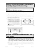
(4) The printhead angle has been factory set. In order to ensure that it is still correct,
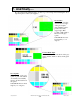
compare the test card with the images on the back page of this document.
N.B. If your test card shows a completely different test image from those on the back
page, you will need to download the correct test image from the Ultra website at
www.ultra.co.uk/support
. This image can then be printed from any paint package on your
PC.
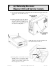
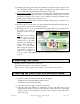
(5) If the printhead angle requires adjustment take note of the current position of the
printhead angle adjustment screws (at the upper rear corner on each nylon side
bracket).
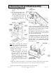
NOTE : There are now two different types
of nylon side brackets – one with 7 adjustment
holes and one with 9 adjustment holes (see diagrams below).
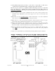
(6) With reference to the relevant diagram (below) and the diagram on the rear page,
decide which of the adjustment holes that the screws need to be moved to.
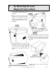
(7) Remove both printhead angle adjustment screws and raise or lower the rear of the
printhead in order to align the required hole in the nylon bracket with the inner hole of
the brass heatsink, and fit and tighten the two printhead adjustment screws.
NOTE : If a printhead angle adjustment screw is moved to a different hole then the other
screw must
be moved to the corresponding hole on the other side of the printhead
assembly.
(8) Steps (3) to (7) should be repeated until the optimum printhead angle is obtained.
TWO TYPES OF NYLON SIDE BRACKETS