REV.2006.04 INSTALL GUIDE AUTOMATIC TRANSMISSION ONLY! www.ultrastarters.com Technical Support: 877-598-2100 ext 1 support@ultrastarters.com Warning!! The system must be placed into Service Mode before any service work is started on the CARBON MONOXIDE MAY CAUSE SERIOUS INJURY, EVEN DEATH! vehicle. It is the sole responsibility of the vehicle owner to ensure that this is done.
INSTALL GUIDE PAGE 2 Table of Contents Table of Contents Component/Feature List Recommend Installation Procedures Wiring Diagrams Wiring Descriptions 6 Pin Connector Auxiliary Connectors Quick Start Installation Basic Installation Important Tach Notes Auto Tach Learn Quick Learn Tach System Reset Programming Overview Entering Program Mode Quick View Programming Program Menus Program Menu 1 (User Settings) Program Menu 2 (Additional Settings) Program Menu 3 (Starter Settings) Program Menu 4 (Tach Settings)
INSTALL GUIDE PAGE 3 Components - Control module - 2 Remote Transmitters - Antenna with built in Program Button and LEDs - 6 pin Main harness - 14 pin auxiliary harness - 3 pin keyless entry harness - 3 pin auxiliary harness (not available on all models) - Owner and Install guide’s - Hood pin switch Feature List - Auto Tach (Tachless, TL series only) learning with Quick Learn - Run Time: 4/15/45 minutes - Door locks: .125s/.
INSTALL GUIDE PAGE 4 Recommended Installation Procedures Remote car starters and alarms should be professionally installed. Review the installation and owner manuals and acquire a vehicle wiring diagram for the vehicle to be worked on. Take a few moments to walk around the vehicle looking for any damages and make note if any are found. Also check other functions such as the lighting system, warning or check engine lights.
PAGE 5 INSTALL GUIDE Recommended Installation Procedures Mounting The Control Module - Never mount the module in the engine compartment. Select a location under the dash to install the main module. Be certain that the module is securely attached and does not obstruct any serviceable areas. Do not force or jam the module into tight places instead of mounting. The module must be free from all moving parts such as brake, clutch and gas pedal linkages.
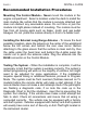
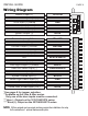
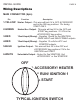
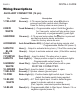
INSTALL GUIDE PAGE 6 Wiring Diagram Starter Output (+) YELLOW Heater/Accessory Output (+) GREEN 12volt Input (+)30amp RED 12volt Input (+)30amp RED Selectable Output (+) WHITE* Ignition Output (+) BLUE Re-arm Output (-)250ma YELLOW Trunk Release Output (-)250ma RED/WHITE Dis-arm Output (-)250ma BROWN Anti-Grind/Starter Kill Output (-)250ma ORANGE Horn***/Siren**** Output (-/+)250ma WHITE/BLUE N/A BLACK/WHITE Door Pin Input (+) PURPLE** Park Light Output (+)10amp WHITE Hood Pin
INSTALL GUIDE PAGE 7 Wiring Diagram *The centre pin of the keyless entry harness is ONLY available with plug-in devices such as the VP-1, DL-3, DL-7 and Data Bus Modules. Overloading this output will damage the remote starter.
INSTALL GUIDE PAGE 8 Wiring Descriptions MAIN CONNECTOR (6pin) Pin Function Description 1-YELLOW Starter Output - This wire will test 0V in OFF, ACCESSORY 2-GREEN 3-RED 4-RED 5-BLUE 6-WHITE and in the ON key positions. 12v during START ONLY. Heater/Acc Output - This wire will test 0V in the OFF and START key positions. 12-14V in the ACCESSORY key position. 12volt Input(30amp) - Supplies 12votls for the IGNITION, PARK LIGHT and SELECTABLE outputs.
INSTALL GUIDE PAGE 9 Wiring Descriptions AUXILIARY CONNECTOR (14 pin) Pin 1-YELLOW 2-RED/ WHITE 3-BROWN 4-ORANGE 5-WHITE/ BLUE 6-N/A 7-PURPLE 8-WHITE 9-GREEN/ WHITE 10-GREEN 11-BLACK 12-PINK 13-BLUE/ WHITE 14-BLUE Function Description Re-arm(-) - 0.75 second pulse output when button is pressed and after remote start shutdown. Used for factory alarm re-arm.(menu 3) Trunk Release(-) - Programmable output.
INSTALL GUIDE PAGE 10 Wiring Descriptions LOCK/ UNLOCK CONNECTOR (3pin red) Pin 1-GREEN 2-RED 3-BLUE Function Description Lock(-) - Programmable LOCK output. (Menu 1) 12volts - 250ma 12volt output. Unlock(-) -Programmable UNLOCK output ANTENNA CONNECTOR (4pin Blue) RF Antenna with Program Button and LEDs AUXILIARY BYPASS CONNECTOR (3pin white) Pin 1-WHITE/ VIOLET 2-BLACK 3-RED Function Description Ground While Running(-) - 250ma ground output while remote starter is active.
INSTALL GUIDE PAGE 11 Step 1 - Connect All Of the Following Wires Main Connector (6pin) YELLOW GREEN RED RED BLUE WHITE* Starter Output - 12volts during start position only. Heater/Acc Output - 12volts in the accessory position off during start and 14volts during run. 12volt 30amp Input - 12volts from ignition harness or battery. 12volt 30amp Input - 12volts from ignition harness or battery. Ignition Output - 12volts in the ignition, start and run positions.
INSTALL GUIDE PAGE 12 Auto Tach/Tachless Learn IMPORTANT! The system must be Tach Learned before remote starting. 1) Turn the ignition key to the “ON” position. The park lights will turn “ON” 2) Start the vehicle with the key. The LEDs on the antenna will turn on if a proper tach signal is detected**, after 30-35 seconds the park lights will flash and the siren will chirp twice to confirm Tach Learn. NOTE: The LEDs will not turn “ON” for Auto Tachless Learn on the TL series.
INSTALL GUIDE PAGE 13 Important Tach Notes Tach Learning the remote starter is one of the most important steps in the installation process. Do not tach learn vehicle while the engine is in high idle. To ensure the best possible tach setting, ensure that the vehicle is at low idle/ normal operating RPM. Vehicles such as Toyota and Honda may idle much higher when the engine is warm compared to starting the vehicle when the engine is cold.
INSTALL GUIDE PAGE 14 System Reset The system reset will clear any changes made to the Program Menu as well as the Tach setting. 1) Turn the ignition key from “Off” to “On” 3 times, ON-OFF-ON-OFFON within three seconds. (Leave the key in the ON position) 2) Press and release the Program Button located on the antenna. The park lights will turn on and the siren or horn (optional) will chirp one time.
INSTALL GUIDE PAGE 15 Entering Program Mode Ignition 3x On/Off On/Off On Press and Release the Program Button For Menu 1, For Menu 2, For Menu 3, For Menu 4, press the press the press the press the button button button button 1) With the ignition in the OFF position, turn the ignition key from “Off” to “On” 3 times, ON-OFF-ON-OFF-ON within three seconds. NOTE: Leave the key in the ON position 2) Press and release the Program Button.
INSTALL GUIDE PAGE 16 Quick View Programming Menu 1 - Press 1 Ignition Lock 2 Siren Output 3 Lock&Unlock Options 4 Unlock/Disarm 5. Passive Locks* 6. Shock Sensor* 7.
INSTALL GUIDE PAGE 17 Menu 1- User Settings Ignition 3x On/Off On/Off On Press and Release the Program Button Press and Release the button for Menu 1 Press and Hold Press and Release the Program Button the Program Button to Change Option Number of Times for the Setting Chosen Setting 1 Ignition Auto Lock 1) Enable 2) Ignition Lock Only *3) Disable 1 Flash/Chirp 2 Flashes/Chirps 3 Flashes/Chirps Doors Lock/Unlock with Ignition key. Doors Lock when ignition is turned “ON” only.
INSTALL GUIDE PAGE 18 Menu 1- User Settings...continued Setting 6 Sensor Enable/Disable (2270/4270/4265 series ONLY) 1) Sensor Disabled *2) Sensor Enabled 1 Flash/Chirp 2 Flashes/Chirps Impact Sensor Disabled Impact Sensor Enabled Press & Release the Program Button 6 Times (Setting 6) Confirmed with 6 LED flashes. Press & Hold the Program Button until the appropriate # of park lights/ siren chirps, then release. Press & Release the Program Button to proceed to the next step.
INSTALL GUIDE PAGE 19 Menu 2- Additional Settings Ignition 3x On/Off On/Off On Press and Release the Program Button Press and Release the button for Menu 2 Press and Release Press and Hold the Program Button the Program Button Number of Times for to Change Option the Setting Chosen Setting 1 Secure Valet Mode (time required to set the system into Service Mode) 1) Secure Valet *2) Normal Valet 1 Flash/Chirp 2 Flashes/Chirps Hold the Program Button for 15 seconds Hold the Program Button for 5 seconds
INSTALL GUIDE PAGE 20 Menu 3- Starter Settings Press and Release the Program Button Ignition 3x On/Off On/Off On Press and Release the button for Menu 3 Press and Release the Program Button Number of Times for the Setting Chosen Press and Hold the Program Button to Change Option Setting 1 Special Door Lock/Unlock Operations (Factory Alarm Rearm). 1) Type 1 2) Type 2 *3) Type 3 1 Flash/Chirp 2 Flashes/Chirps 3 Flashes/Chirps Unlock before start. Lock pulse after start and shutdown.
INSTALL GUIDE PAGE 21 Menu 3- Starter Settings - continued Setting 5 Maximum Crank Time 1) 10 Seconds 2) 3 Seconds *3) 5 Seconds 1 Flash/Chirp 2 Flashes/Chirps 3 Flashes/Chirps 10 sec max time that the starter will stay engaged. 3 sec max time that the starter will stay engaged. 5 sec max time that the starter will stay engaged. Press & Release the Program Button 5 Times (Setting 5) Confirmed with 5 LED flashes.
INSTALL GUIDE PAGE 22 Menu 4- Tach Settings Ignition 3x On/Off On/Off On Press and Release the Program Button Press and Release the button for Menu 4 Press and Hold Press and Release the Program Button the Program Button to Change Option Number of Times for the Setting Chosen Setting 1 Low Idle Learn- Same function as doing the Quick Tach Learn. This option is used for vehicles that maintain a High or Erratic idle after starting and need more than 30 seconds to establish a stable idle.
PAGE 23 INSTALL GUIDE Remote Transmitter Learn STEP 1 - Within 3 seconds turn the ignition key to the “ON” position three times leaving “ON” the third time. STEP 2 - Press and hold the Program Button. The park lights will turn “ON” and the siren will chirp once. Continue to hold the Program Button, the park lights will turn “OFF” and the siren will chirp 5 times quickly.
INSTALL GUIDE PAGE 24 Shock Sensor 2270/4270/4265 series Shock Sensor Programming/ Adjustment To enter shock sensor programming: Press and hold the and the buttons for three seconds. The park lights will flash and the siren will three times. While the park lights are “ON”, strike the vehicle with the amount of force wanted to trigger the alarm. NOTE: The siren will chirp 3 times each time the system detects impact.
PAGE 25 Install Notes INSTALL GUIDE
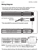
INSTALL GUIDE PAGE 26 Door Lock Relay Wiring Diagrams Negative Type Door Locks 250ma Vehicle Lock/Unlock Switch Lock To Control Relay or Actuators Un lock Green Blue Negative Door Locks (More Than 250ma) Fused +12V Vehicle Lock/Unlock Switch Ground 87 Green 87 87a 86 87a 86 85 Blue Un Lock lock 30 85 30 To Control Relay or Actuator Positive Type Door Locks Vehicle Un Lock Lock/Unlock lock Switch Fused +12V Green 87 87 87a 86 Blue 87a 85 30 86 85 30 To Control Relay or Actuator
INSTALL GUIDE PAGE 27 Door Lock Relay Wiring Diagrams 5 Wire / Reverse Polarity Type Door Locks Fused +12V 87 Green 87 87a 87a 86 Vehicle Lock/Unlock Switch 86 85 Blue 30 Lock 85 30 x Cut Un lock To Actuator x Cut Aftermarket Doorlock Actuators Ground 87 87a 86 85 30 Vacuum Type Door Locks DIAGNOSTICS Ground Fused +12V Blue Lock Un lock 87 87 87a 87a 86 85 86 30 85 30 x Cut To Vacuum Pump 13 Green NOTE: When installing relays always use a fused power source.
INSTALL GUIDE PAGE 28 DIAGNOSTICS If the remote starter does not activate when the start button is pressed the park lights will flash a diagnostic to indicate what shutdown input has been triggered. For example: If the button is pressed the park lights flash 3 times slowly. Looking at the chart below this would indicate that the system is in Service Mode, simply follow the instructions listed in the owners manual on exiting Service Mode and the remote starter will begin to function as normal.