ULTRA 3 (UL) INSTRUCTION MANUAL
ULTRA 3 UL (FIFTH EDITION) June 2011 Part Number M-170-3-005-0U COPYRIGHT © Pulsar Process Measurement Limited, 2005 - 11. All rights reserved. No part of this publication may be reproduced, transmitted, transcribed, stored in a retrieval system, or translated into any language in any form without the written permission of Pulsar Process Measurement Limited.
Contents Chapter 1 Start Here… ......................................................................................................................................... 1 About this Manual ........................................................................................................................................... 1 About the Ultra 3.............................................................................................................................................
Top Level Menu.....................................................................................................................................52 Application Menu ..................................................................................................................................53 Relays Menu...........................................................................................................................................54 Data Logs Menu.............................................
Menu System and Parameter Guide ........................................................................................................... 113 Top Level Menu .................................................................................................................................. 113 Application Menu ................................................................................................................................ 114 Relays Menu ........................................................
Velocity................................................................................................................................................ 169 Stability Parameters .................................................................................................................................... 170 Damping .............................................................................................................................................. 170 Indicator ................................
Chapter 1 Start Here… Congratulations on your purchase of a Pulsar Ultra 3. This quality system has been developed over many years and represents the latest in high technology ultrasonic level measurement and control. It has been designed to give you years of trouble free performance, and a few minutes spent reading this operating manual will ensure that your installation is as simple as possible. About this Manual It is important that this manual is referred to for correct installation and operation.
About the Ultra 3 Ultra 3 is three units in one. Ultra 3 is a brand new concept in ultrasonic level measurement. Within its memory are all the functions and settings of three different and completely separate ultrasonic devices. The Ultra 3 does not offer a multiple range of functions blended together which lead to complicated calibration and a compromise to the specification, Ultra 3 is the first ever system to offer the ability to dedicate the functionality of the unit to any of three specific duties i.
Functional Description Ultra 3 sends a transmit pulse to the transducer, which emits an ultrasonic pulse perpendicular to the transducer face, and the returned echo is sent back to the Ultra 3. The time taken to receive the echo is measured and the distance from the transducer face to the surface being monitored is calculated. Ultra 3 can measure from zero to 131 feet (40m) from the face of the transducer to the surface being monitored, dependent on the application chosen and transducer used.
How to use this Manual 1. Read the installation and operating instructions contained in, Chapters 2 and 3, carefully, they are applicable in every use of this product. 2. Decide which “task” you wish your Ultra 3 to perform for you and then configure the unit using “Ultra Wizard” as described in Chapter 4. 3. Move directly to the appropriate chapter of this manual as listed below, for details on how to program Ultra 3 using the “Quick Set Up” Menu.
Product Product Specification Physical Wall Mount Outside dimensions Weight Enclosure material/description Cable entry detail Fascia Mount Outside dimensions Weight Enclosure material/description Transducer cable extensions Maximum separation Environmental Mounting - Wall Mount - Fascia Mount Relative Humidity (IP Rating) - Wall Mount - Fascia Mount Altitude Max. & min. temperature (electronics) Flammable atmosphere approval Approvals UL CE approval Performance Accuracy Resolution Max. range Min.
Outputs Analogue output Isolated (floating) output of 4-20 mA or 0-20 mA into 500Ω (user programmable and adjustable) 0.
EC Declaration of Conformity Wall Mount Page 7
Fascia Mount Page 8
Chapter 2 Installation Power Supply Requirements Ultra 3 can operate from AC supply or from a DC battery and is designed for use in temperatures between -4oF to +140oF (-20oC to +50oC). The AC is 115V +5% / -10% 50/60Hz. The DC is 18-30V. In all cases the Ultra 3 will typically consume 6W of power, with a maximum of 10W.
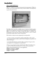
Location All electronic products are susceptible to electrostatic shock, so follow proper grounding procedures during installation. Ultra 3 must be mounted in a non-hazardous (safe) area, and the transducer fitted in the hazardous area. FM APPROVED TRANSDUCERS Class I, Div. 1, Group A, B, C & D Class II, Div. 1, Group E, F & G When choosing a location to mount the enclosure, bear in mind the following: • Ensure that the Ultra 3 is installed in a “Safe”, non-hazardous, area.
Dimensions Wall Mount The dimensions of the wall fixing holes are as shown below. Ultra 3 should be mounted by drilling three holes suitable for size 8 screws (length to suit your application), and fixing the top screw in place. Hang the unit on this and fix the two remaining screws by removing the terminals access cover to access the pre-drilled holes.
The full dimensions of the enclosure are as shown below.
Cable Entry There are 4 cable gland knock-outs on the base of the wall mount Ultra 3 (3 x 0.79" (20mm), 1 x 0.63" (16mm) and 4 on the rear (4 x 0.73" (18mm)). Select which ones you wish to use, and remove them by using a circular cutter, such as a tank cutter. Take care not to damage the circuit board inside while undertaking this. Do not use a hammer, as this may cause damage to the enclosure.
Fascia Mount The Fascia mount Ultra 3 should be installed by cutting a hole in the panel, as detailed below, and securing the unit with the fixings supplied. The full dimensions of the Fascia mount enclosure are as shown below.
Important Information When mounting the fascia mount unit in to a panel, in order to maintain the panel IP rating the panel should be of smooth/painted finish and be machined, as per the details contained in this manual. Fit the unit through the hole then, using the components supplied place a plain washer then a spring washer followed by an elongated nut to each of the 4 off M3 threaded studs and tighten to 2.5lb in. (0.28Nm) Care should be taken not to overtighten the screws.
Fascia Mount The terminal details are as illustrated below. Important Information All terminal connection screws should be tightened to 4.5in.lbs. (0.5Nm). Care should be taken not to over tighten the screws.
Terminal Connections Important Information All terminal connection screws should be tightened to 4.5in.lbs. (0.5Nm). Care should be taken not to overtighten the screws. Power Ultra 3 can operate from mains AC and automatically from DC or battery backup in the event of power failure, or can be operated permanently from DC or batteries. Important Information The protective earth must be connected prior to any other cabling taking place.
Transducer The transducer should be installed, and connected, in accordance with the installation instructions contained in the Transducer User Guide. The entire range of, standard dB transducers are certified for use in hazardous areas and different models, for each, are available for use in Zone 1 or Zone 0.
ATEX For EEx m (Zone 1) applications a transducer certified to Sira 02ATEX5104X is used, and must be supplied via a 4000A breaking fuse, which is fitted as standard to the Ultra3. For EEx ia (Zone 0) a transducer certified to Sira 02ATEX2103X is used, which must be connected to the Ultra 3 via an external Zener barrier. See transducer label for certification details.
Fuse Location Wall mount The mains fuse is located, inside the terminal compartment, to the left of the mains terminals, as illustrated below. Fascia mount The mains fuse is located under the removable cover at the bottom of the unit, as illustrated below.
Important Information The rear metal case of the fascia unit must be connected to earth via the earthing stud located on the rear of the unit, see drawing above, using wiring to meet local requirements. Before applying AC power (mains), make sure the supply is 115V AC. Never operate the Ultra 3 with terminal access exposed. An external switch or circuit breaker should be installed near to the Ultra 3 to allow the supply to be removed during installation and maintenance.
Preparation for Operation Before switching on, check the following: Ultra 3 is mounted correctly and is in a ‘safe’ area. The power supply is correctly installed. The relays are connected correctly. Maintenance There are no user serviceable parts inside Ultra 3, except the mains fuse. If you experience any problems with the unit, then please contact Pulsar Process Measurement for advice.
Chapter 3 How To Use Your Ultra 3 Operating the Controls Display The display provides information on the current mode of operation, and status of the remote communication. While in the Run Mode it will display the current level reading and its units of measure, along with status messages with regards to the Transducer, Echo reception and Fail Safe Mode. Additionally it can be programmed to provide status messages on alarms, pumps etc.
3) Auxiliary Display, scrolling twelve digit display. Run Mode, displays measurement units (P104), status messages on signal and transducer, detail of Hot Key function selected. It can be also programmed to provide notification messages on alarms and pumps etc. for full details please refer to Display Parameters in the relevant parameter listing. Program Mode, displays Menu and Sub Menu headings, parameter details and options.
Program Mode This mode is used to set up the Ultra 3 or change information already set. You must use either the built-in keypad (standard) or alternatively the unit can be set up with a PC via the RS 232 Serial Interface. Entering a value for each of the parameters that are relevant to your application provides all the programming information.
Hot Keys There are five hot keys on the keypad, which can be used to quickly access common parameters for viewing only, while in Run Mode. Pressing the hot key once will display the first parameter, then repeated pressing will display the others, then the Ultra 3 reverts to Run Mode. In program mode, they have different functions, the functions are shown below. Hot Key Run Mode When application is Flow, view non-resettable totaliser. View and reset the resettable totaliser.
Menu Keys The menu keys have the following functions: Menu Key Function 1) Arrow keys for moving left and right around the menu system. 2) Used in test mode to simulate the level moving up and down. 1) Used to confirm each action (for example select a menu option) or when entering a parameter number or value. 2) Used to confirm questions asked by your Ultra 3 such as before restoring factory defaults. Used to navigate up a level in the menu system, and back to run mode.
There are two means of editing parameters, directly or using the menu system. Each is now described. Using the Menu System The menu system has been designed to make the changing of parameters very simple. There are two levels of menu: Main Menu and Sub Menu. On the display there is a line of text that displays the menu system. Pressing the arrow keys scrolls the display between the top-level menu items, (as shown below, starting at Ultra Wizard).
Note You can tell which part of the menu system you are in, as the up/down level indicators, (arrows) next to the bargraph will indicate as follows: • Top level menu: Down arrow on, to indicate you can move down. • Sub-menu: Up and Down arrows on, to indicate you can move up to the top level, and down to parameter level. • Parameter Level: Up arrow on, to indicate you can move up to submenu level. • Parameter Editing: No arrows on.
Test Mode Test mode is used to simulate the application and confirm that all parameters and relay setpoints have been entered as expected. During simulation, there is a choice of whether the relays will change state (hard simulation) or not (soft simulation), but the LED’s will always change colour as programmed, and the mA output will change in accordance to the chosen mode of operation.
Using the RS232 Serial Interface The RS232 serial interface is used to communicate between the Ultra 3 and a PC using the optional Ultra PC and other associated Pulsar software packages, to obtain information such as data logging and view echo traces upload, download and save parameter files. In addition it can also be used to control or obtain information using a standard PC or other computer base equipment.
Examples of other commands you can use are: /LEVEL (shows current level) /SPACE (shows current space) /HEAD (shows current OCM head) /FLOW (shows current OCM flow) /TEMPERATURE (shows current temperature) /CURRENTOUT (show the mA output value) /CURRENTIN (show the mA input value) /BACKUP1 (take backup of parameters to area 1) /BACKUP2 (take backup of parameters to area 2) /RESTORE1 (restore parameters from area 1) /RESTORE2 (restore parameters from area 2) Page 32
Parameter Defaults Factory Defaults Factory Defaults When first installing the Ultra 3, or subsequently moving or using the unit on a new application, before proceeding to program the unit for its intended application it is recommended that you ensure that all parameters are at their default values by completing a Factory Defaults P930, as described in the relevant unit type parameter guide. When you first switch Ultra 3 on, it will be reading the distance from the face of the transducer to the surface.
This page left blank intentionally Page 34
Chapter 4 Ultra Wizard The Ultra Wizard menu allows you to turn Ultra 3 into anyone of three dedicated ultrasonic devices to exactly suit the requirements of your application. Ultra Wizard Menu To access the Ultra Wizard you need to go from Run Mode to Program Mode. Enter Program Mode First you need to go from run mode into program mode. Assuming the passcode is the default 1997, then, you should enter this. Choose Ultra Wizard Now you need to go into the Ultra Wizard.
Lev/Vol If you require to set up a level or volume application, with or without a choice of control functions then press “1” followed by “ENTER” the message “Loading ***” will be displayed and your Ultra 3 will be configured as a Level Star 110. Confirmation that configuration has been completed will be given by the unit type, software version and serial number being displayed briefly on the LCD and the unit advancing to the relevant “Quick Setup” menu.
Pump If you require to set up a pump application then press “2” followed by “ENTER” the message “Loading ***” will be displayed and your Ultra 3 will be configured as a Vantage 100. Confirmation that configuration has been completed will be given by the unit type, software version and serial number being displayed briefly on the LCD and the unit advancing to the relevant “Quick Setup” menu. For full details on how to programme the Vantage 100, using the Quick Setup Menu, please proceed to Chapter 6 Pump.
Flow Oracle 160 The Flow Oracle 160 open channel flowmeter provides comprehensive flow monitoring with data logging and control functions for a complete range of flumes, weirs and channels. Flow calculations to the British Standard BS3680 are available within the software together with calculations for a wide variety of other primary elements. Also available within the unit is a customised 32 point calibration routine which also permits the flow measurement of non - standard flumes and weirs.
Chapter 5 Level / Volume When Ultra Wizard = 1 Level/Volume Ultra 3 is configured as a Level Star 110 Quick Setup This quick set-up guide shows you how to get up and running within a few minutes of installing your Level Star 110. Before proceeding ensure that Ultra Wizard = 1 Level/Volume (Level Star 110). For further details see Chapter 4 Ultra Wizard. Enter Program Mode First you need to go from run mode into program mode. Assuming the passcode is the default 1997, then you should enter this.
Note If you have already setup a common application, then there will be a number shown other than 0, and you will see messages showing what the current setup is. If you want to reset this and start again, press 0 (which will reset all the quick setup parameters), otherwise pressing ENTER will allow you to edit the parameters that have been set. Choose Your Application There are two categories of application, which are all described later in this chapter.
The Quick Setup Menu detailing the questions you will be asked when setting up your Level Star, via the Quick Setup is shown below. Quick Setup Menu Quick Setup Application 1 = Level 2 = Volume 0 = No Control 1 = Control Down 2 = Control Up No. of Control Relays 1 = 1 Control Relay 2 = 2 Control Relay 3 = 3 Control Relay For each Cntl.
Parameter P101 Transducer P102 Material Default 2 = dB6 1 = liquid P104 Measnt. Units 4 = feet P105 Empty Level 19.685 feet P106 Span 18.701 feet Description Type of transducer being used. Material in the vessel, either liquid or solid. If the solid lays flat then it can be entered as liquid. Select units to be used for programming measurement information. Distance from the face of the transducer to the material at the bottom of the vessel.
For More Options Hit Enter Parameter P213 / P214 Relay 1 ON/OFF setpoints P223 / P224 Relay 2 ON/OFF setpoints P233 / P234 Relay 3 ON/OFF setpoints P830 mA Out Range Default Factory preset as a % to appropriate level according to the span already entered. See tables below Factory preset as a % to appropriate level according to the span already entered. See tables below Factory preset as a % to appropriate level according to the span already entered. See tables below 2= 4 to 20 mA P870 Fill Damping 32.
The default values used for determining the relay setpoints, when setting Alarms and Control relays, via the Quick Setup menu are entered as a % of span and are as follows. Cntl. Down Cntl. Down Number of Cntl Relays One Two Cntl. Down Three Application Cntl. Up Cntl. Up Number of Cntl Relays One Two Cntl. Up Three Application Relay Function Alarm Alarm Alarm Alarm Page 44 Relay I.D.
Example 1 Level Monitoring with Alarms A vessel, containing a liquid that has a variation in level that is to be monitored, with a high level alarm set on Relay 1, and low level alarm set on Relay 2. empty distance (P105), 11.0 feet 100%, span (P106), 10.0 feet 85% , high alarm on (P213), 8.5 feet 80% , high alarm off (P214), 8.0 feet 15% , low alarm off (P224), 1.5 feet 10% , low alarm on (P223), 1.0 feet 0% , empty level In this example, when the level rises to 8.
To program the Level Star 110 for Example 1 Level Monitoring with alarms by using the Quick Setup menu proceed as follows. If required access the Program Mode Key in the passcode 1997 and press ENTER Using the ‘right’ arrow key go to the Quick Setup menu press ENTER and as prompted, by the questions, select the relevant option and ENTER. Question Level/Volume Control No.
Example 2 Level Monitoring and Control (up or down) A vessel, containing a liquid that has a variation in level that is to be monitored, and when the level reaches a specific point, the vessel is pumped down, with the fluid being transferred to another process. The pump will be assigned to Relay 1 a High Alarm to Relay 2 and Low Alarm to Relay 3. empty distance (P105), 11.0 feet 100%, span (P106), 10.0 feet 85%, high alarm on (P223), 8.5 feet 80%, high alarm off (P224), 8.
To program the Level Star 110 for Example 2 Level Monitoring and Control by using the Quick Setup menu proceed as follows. If required access the Program Mode Key in the passcode 1997 and press ENTER Using the ‘right’ arrow key go to the Quick Setup menu press ENTER and as prompted, by the questions, select the relevant option and ENTER. Question Level/Volume Control No. of Controls Control No. 1 No. of Alarms Type Alarm 1 Alarm No. 1 Type Alarm 2 Alarm No.
Example 3 Volume Application A cylindrical tank with a diameter of 7 feet and a flat base that is typically used to temporarily hold liquid, and you wish to know the volume of liquid. You also require a high and low alarm and when the level reaches a specific point, the vessel is pumped down, with the fluid being transferred to another process. empty distance (P105), 11.0 feet 100%, span (P106), 10.0 feet 85%, high alarm on (P223), 8.5 feet 80%, high alarm off (P224), 8.
To program the Level Star 110 for Example 3 Volume Application with Control by using the Quick Setup menu proceed as follows. If required access the Program Mode Key in the passcode 1997 and press ENTER Using the ‘right’ arrow key go to the Quick Setup menu press ENTER and as prompted, by the questions, select the relevant option and ENTER. Question Level/Volume Control No. of Controls Control No. 1 No. of Alarms Type Alarm 1 Alarm No. 1 Type Alarm 2 Alarm No.
Note If relay setpoints do not meet the exact requirements of the application, they can be modified to suit by pressing ENTER when, “For More Options Hit Enter”, is displayed and entering new values to relay setpoints as required. Alternatively the relevant relay setpoint can be accessed either by the main menu system or directly via parameter number and changed as necessary.
Menu System and Parameter Guide This section outlines all parameters available in the Level Star, as they appear in the menu system. Shown below is a set of charts illustrating the meny system and location of all parameters available in the Level Star. For further details and full description of all parameters refer to Chapter 8 Parameter Listing and Descriptions.
Application Menu Operation Distances P100 Mode P104 Measurement Units P101 Transducer P102 Material P105 Empty Level P106 Span P107 Near Blanking P108 Far Blanking Page 53
Relays Menu Page 54 Relay 1 Relay 2 Relay 3 P210 Type P220 Type P230 Type P211 Function P221 Function P231 Function P212 Alarm ID or Pump Group P222 Alarm ID or Pump Group P232 Alarm ID or Pump Group P213 Set 1 P223 Set 1 P233 Set 1 P214 Set 2 P224 Set 2 P234 Set 2 P217 Closures P227 Closures P237 Closures P218 Fail Safe P228 Fail Safe P238 Fail Safe P219 R2 Max.Rate If P220=2 P229 R3 Max.Rate If P230=2 P239 R4 Max.
Data Logs Menu Temperature P580 Min. Temp P581 Min. Temp. Date P582 Min. Temp. Time P583 Max. Temp. P584 Max. Temp. Date P585 Max. Temp.
Volume Menu Conversion Breakpoints Tables P600 Vessel Shape P610 Level Bkpt. 1 P696 Reset Bkpts. P601 As Required Vol. Dimension 1 P611 Vol. Bkpt. 1 P602 As Required Vol. Dimension 2 P603 As Required Vol. Dimension 3 P604 Calculated Volume P612, 614, 616, 618, 620, 622, 624, 626, 628, 630, 632, 634, 636, 638, 640, 642, 644, 646, 648, 650, 652, 654, 656, 658, 660, 662, 664, 666, 668, 670 Level Bkpts. 2 to 31 P606 Correct.
Display Menu Options Fail Safe Auxiliary Bargraph P800 Display Units P808 Fail Mode P810 Units P829 Bargraph P809 Fail Time P811 Alarms P801 Decimal Places P812 Pumps P802 Display Offset P813 Control P804 Display Conversion P814 Misc.
Compensation Menu Offset Temperature Velocity P851 Measurement Offset P852 Temperature Source P860 Sound Velocity P854 Fixed Temperature P861 Calibration Distance 1 Stability Menu Damping Indicator Rate Filters P870 Fill Damping P872 Fill Indicator P874 Rate Update P880 Gate Mode P871 Empty Damping P873 Empty Indicator P875 Rate Time P881 Fixed Distance P876 Rate Distance P882 Process Filter P877 Rate Value P884 Peak Percent P878 Lower Cutoff Page 58
Echo Processing Menu Xdr. 1 Status P900 Xdr.
System Menu Passcode Backup System Info Date & Time P921 Enable Code P925 Parameter Backup P926 Software Revision P931 Date P922 Passcode LED Colour Daylight Saving P935 Off Colour P970 DST Enable P936 Alarm Colour P971 DST Difference P937 Pump Colour P972 DST Start Time P929 Site Ident. P938 Control Colour P973 Start Day P930 Factory Default P939 Misc.
Device Comm Menu RS232 Set Up RS485 Set Up (Optional) P061 Comms Baud If Comms. Type MODBUS Remote Alarm If Comms. Type PROFIBUS P144 Call Type P130 Device Mode P145 Tel. No. 1 P131 Protocol P146 Tel. No. 2 P132 Device Address P132 Device Address P147 Tel. No. 3 P133 Device Baud P148 Timed Out P134 Parity P149 Retry No.
Test Menu Simulation Hardware P980 Simulate P990 Self Test P981 Increment P991 Hardware Test P982 Rate P992 mA Out Test P983 Start Level P994 Transducer Test P984 Incremental Change P995 Keys Test P996 Relay Test Page 62
Chapter 6 Pump When Ultra Wizard = 2 Pump Ultra 3 is configured as a Vantage 100 Quick Setup This quick set-up guide shows you how to get up and running within a few minutes of installing your Vantage 100. Before proceeding ensure that Ultra Wizard = 2 Pump (Vantage 100). For further details see Chapter 4 Ultra Wizard. Enter Program Mode First you need to go from run mode into program mode. Assuming the passcode is the default 1997, then you should enter this.
Note If you have already setup a common application, then there will be a number shown other than 0, and you will see messages showing what the current setup is. If you want to reset this and start again, press 0 (which will reset all the quick setup parameters), otherwise pressing ENTER will allow you to edit the parameters that have been set. Choose Your Application There are three categories of application, which are all described later in this chapter.
The Quick Setup Menu detailing the questions you will be asked when setting up your Vantage 100 unit, via the Quick Setup is shown below.
Parameter P101 Transducer P104 Measnt. Units Default 2 = dB6 4 = feet P105 Empty Level 19.685 feet P106 Span 18.701 feet Description Type of transducer being used. Select units to be used for programming measurement information. Distance from the face of the transducer to the material at the bottom of the vessel. Distance from the empty level (0% full) to span (100% full).
The default values used for determining the relay setpoints, when setting Alarms and Pump relays, via the Quick Setup menu are entered as a % of span and are as follows. Pump Down Pump Down Number of Pumps One Two Pump Down Three Application Pump Up Pump Up Number of Pumps One Two Pump Up Three Application Relay Function Alarm Alarm Alarm Alarm Relay I.D.
Example 1 Level Monitoring with Alarms A vessel, containing a liquid that has a variation in level that is to be monitored, with a high level alarm set on Relay 1, and low level alarm set on Relay 2. empty distance (P105), 11.0 feet 100%, span (P106), 10.0 feet 85% , high alarm on (P213), 8.5 feet 80% , high alarm off (P214), 8.0 feet 15% , low alarm off (P224), 1.5 feet 10% , low alarm on (P223), 1.0 feet 0% , empty level In this example, when the level rises to 8.
To program the Vantage 100 for Example 1 Level Monitoring with alarms by using the Quick Setup menu proceed as follows. If required access the Program Mode Key in the passcode 1997 and press ENTER Using the ‘right’ arrow key go to the Quick Setup menu press ENTER and as prompted, by the questions, select the relevant option and ENTER. Question Level, Pump Up or Down No.
Example 2 Sump Control (pump down) A sump is typically used to temporarily hold water or effluent, and when the level reaches a specific point, the sump is pumped down, with the fluid being transferred to another process. empty distance (P105), 11.0 feet 100%, span (P106), 10.0 feet 85% , high alarm on (P233), 8.5 feet 80% , high alarm off (P234), 8.0 feet 50%, pump 2 on (P 223), 5.0 feet 30%, pump 1 on (P 213), 3.0 feet 20% , pump 1+2 off (P214, 224), 2.
To program the Vantage 100 for Example 2 Sump control (pump down) using the Quick Setup menu proceed as follows. If required access the Program Mode Key in the passcode 1997 and press ENTER Using the ‘right’ arrow key go to Quick Setup menu press ENTER and as prompted, by the questions, select the relevant option and ENTER. Question Level, Pump Up or Down No. of Pumps Pump Duty Pump No. 1 Pump No. 2 No. of Alarms Type Alarm 1 Alarm No.
Example 3 Reservoir Control (pump up) A reservoir is typically used to temporarily hold liquid, and when the level reaches a specific low point, the reservoir is pumped up. empty distance (P105), 11.0 feet 100%, span (P106), 10.0 feet 80%, pump 1+2 off (P224, 234), 8.0 feet 70%, pump 1 on (P 223), 7.0 feet 50%, pump 2 on (P 233), 5.0 feet 15% , low alarm off (P214), 1.5 feet 10% , low alarm on (P213), 1.
To program the Vantage 100 for Example 3 Reservoir Control (pump up) by using the Quick Setup menu proceed as follows. If required access the Program Mode Key in the passcode 1997 and press ENTER Using the ‘right arrow key go to Quick Setup menu press ENTER and as prompted, by the questions, select the relevant option and ENTER. Question Level, Pump Up or Down No. of Pumps Pump Duty Pump No. 1 Pump No. 2 No. of Alarms Type Alarm 1 Alarm No.
Menu System and Parameter Guide This section outlines all parameters available in the Vantage 100, as they appear in the menu system. Shown below is a set of charts illustrating the meny system and location of all parameters available in the Vantage 100. For further details and full description of all parameters refer to Chapter 8 Parameter Listing and Descriptions.
Application Menu Operation Distances P100 Mode P104 Measurement Units P101 Transducer P102 Material P105 Empty Level P106 Span P107 Near Blanking P108 Far Blanking Page 75
Relays Menu Page 76 Relay 1 Relay 2 Relay 3 P210 Type P220 Type P230 Type P211 Function P221 Function P231 Function P212 Alarm ID or Pump Group P222 Alarm ID or Pump Group P232 Alarm ID or Pump Group P213 Set 1 P223 Set 1 P233 Set 1 P214 Set 2 P224 Set 2 P234 Set 2 P215 Set 3 As Required P225 Set 3 As Required P235 Set 3 As Required P216 Allocat. P226 Allocat. P236 Allocat. P217 Closures P227 Closures P237 Closures P218 Fail Safe P228 Fail Safe P238 Fail Safe P219 R1 Max.
Data Logs Menu Temperature P580 Min. Temp P581 Min. Temp. Date P582 Min. Temp. Time P583 Max. Temp. P584 Max. Temp. Date P585 Max. Temp.
Display Menu Options Fail Safe Auxiliary P800 Display Units P808 Fail Mode P810 Units P809 Fail Time P811 Alarms P801 Decimal Places P812 Pumps P802 Display Offset P813 Control P804 Display Conversion P814 Misc.
Compensation Menu Offset Temperature Velocity P851 Measurement Offset P852 Temperature Source P860 Sound Velocity P854 Fixed Temperature Stability Menu Damping Indicator Rate Filters P870 Fill Damping P872 Fill Indicator P874 Rate Update P880 Gate Mode P871 Empty Damping P873 Empty Indicator P875 Rate Time P881 Fixed Distance P876 Rate Distance P882 Process Filter P877 Rate Value P884 Peak Percent P878 Lower Cutoff Page 79
Echo Processing Menu Xdr. 1 Status P900 Xdr.
System Menu Passcode Backup System Info Date & Time P921 Enable Code P925 Parameter Backup P926 Software Revision P931 Date P922 Passcode LED Colour Daylight Saving P935 Off Colour P970 DST Enable P936 Alarm Colour P971 DST Difference P937 Pump Colour P972 DST Start Time P929 Site Ident. P938 Control Colour P973 Start Day P930 Factory Default P939 Misc.
Device Comm Menu RS232 Set Up RS485 Set Up (Optional) P061 Comms Baud If Comms. Type MODBUS Remote Alarm If Comms. Type PROFIBUS P145 Tel. No. 1 P130 Device Mode P146 Tel. No. 2 P131 Protocol P132 Device Address P132 Device Address P147 Tel. No. 3 P133 Device Baud P148 Timed Out P134 Parity P149 Retry No.
Test Menu Simulation Hardware P980 Simulate P990 Self Test P981 Increment P991 Hardware Test P982 Rate P992 mA Out Test P983 Start Level P994 Transducer Test P984 Incremental Change P995 Keys Test P996 Relay Test Page 83
This page left blank intentionally Page 84
Chapter 7 Flow When Ultra Wizard = 3 Ultra 3 is configured as a Flow Oracle Quick Setup This quick set-up guide shows you how to get up and running within a few minutes of installing your Flow Oracle 160. Enter Program Mode First you need to go from run mode into program mode. Assuming the passcode is the default 1997, then you should enter this. Before proceeding ensure that Ultra Wizard = 3 Flow (Oracle 160). For further details see Chapter 4 Ultra Wizard.
Note If you have already setup a common application, then there will be a number shown other than 0, and you will see messages showing what the current setup is. If you want to reset this and start again, press 0 (which will reset all the quick setup parameters), otherwise pressing ENTER will allow you to edit the parameters that have been set. Choose Your Application There are five categories of Primary Measuring Device, which are all described in this chapter.
To set-up an application for a device contained in special, choose 5. You then need to select the primary measuring device for your application from the following available options: palmer bowlus flume, H-flume or a V notch, other than BS3680. For devices which do not match any of the above devices the application can be setup using a universal flow calculation, to select this option choose 6.
The Quick Setup Menu detailing the questions you will be asked, when setting up your Flow Oracle 160, via the Quick Setup is shown below. Quick Setup Menu Quick Setup PMD Type 0 = Off (No Calculation) 1 = Exponential 2 = BS3680 Flumes 3 = BS3680 Weirs 4 = Not Available 5 = Special 6 = Universal Exponential 1 = Supp. Rect. 2 = Trapezoid 3 = Venturi 4 = Parshall 5 = Leopold L. 6 = V-Notch 7 = Other BS3680 Flumes 1 = Rectangular 2 = Rect.
Parameter P101 Transducer P706 Volume Units Wait ….. Default Description 1= dB Mach 3 Type of Transducer to be used. 6 = Mil USG Units of flow as on display and used for calculations. 1=litres 2 = cubic metres 3=cubic feet 4 = UK gallons 5=US gallons 6 = Mil.USG Units of time that volume units will be displayed and calculated in. 1= units/sec. 2= units/min. 3= units/hour 4= units/day Units used to enter dimensions, and displayed where appropriate.
Parameter P823 Totaliser Multiplier Default 1= /1000 Description Sets the factor by which the calculated volume will be divided or multiplied by before being displayed. 1 = /1000 2 = /100 4 = *1 3 = /10 5 = *10 6 = *100 7 = *1,000 8 = *10,000 9 = *100,000 10 = *1,000,000 The remaining parameters required to finalise the setup of your application will follow on immediately from the above.
For More Options Hit Enter Parameter P213 / P214 Relay 1 ON/OFF P223 / P224 Relay 2 ON/OFF P233 / P234 Relay 3 ON/OFF P708 Flow Decimal P709 Flow Cut Off P830 mA Out Range P870 Fill Damping P871 Empty Damping Set Value depends on application Description Set required Alarm Setpoints. depends on application Set required Alarm Setpoints. depends on application Set required Alarm Setpoints.
Exponential Devices If the primary measuring device is a simple exponential device then an exponent value is required. The Flow Oracle 160 will automatically enter the exponent value for the device chosen as detailed in the table below. Exponent Type Suppressed Rectangular Weir (Without End Contractions) Exponent P717 1.50 Automatically set Cipolletti (Trapezoidal) Weir 1.50 Automatically set Venturi Flume 1.
Point of Measurement The transducer must be above the maximum head P704 by at least the near blanking distance P107. For Suppressed/ Contracted Rectangular, Trapezoidal and V-notch, weirs, the head is measured upstream at a minimum distance of 3 times maximum head from the weir plate to ensure the surface of the liquid is not affected by turbulence or drawdown. (See DRWG.
For a Leopald Lagco flume the head is measured at a point upstream of the beginning of the converging section as detailed in the table below. (See DRWG 4 ) Flume Size Mm inches 100 - 305 4 - 12 380 15 455 18 530 21 610 24 760 30 915 36 1065 42 1220 48 1370 54 1520 60 1675 66 1830 72 Point of Measurement mm inches 25 1.0 32 1.3 38 1.5 44 1.8 51 2.1 64 2.5 76 3.0 89 3.5 102 4.0 114 4.5 127 5.0 140 5.5 152 6.
Calculations ABSOLUTE If the flow calculation is to be absolute P702 = 1 the flow will be calculated using the formula (s) as follows: Exponent Type Suppressed Rectangular Weir (Without End Contractions) Cipolletti (Trapezoidal) Weir Venturi Flume Parshall Flume Leopold Lagco Flume Formula Q=KLhx Where: Q =Flow K=K factor L=crest length of weir h=head x =exponent Q=KLhx Where: Q =Flow K=K factor L=crest length of weir h=head x =exponent Q=Khx Where: Q =Flow K=K factor h=head x =exponent Q=Khx Where: Q
Exponent Type V-Notch Weir Other Contracted Rectangular Weir (With End Contractions) Formula Q=Khx Where: Q =Flow K=K factor h=head x =exponent Q=Khx Q=K(L-0.2*h)hx Where: Q =Flow K=K factor L=crest length of weir h=head x =exponent Exponent 2.50 Automatically selected by Flow Oracle Enter value as required 1.50 Automatically selected by Flow Oracle K Factor Automatically calculated, dependent on measurement, flow and time units chosen.
Example 1 ‘V’ Notch Weir In this example it is required to calculate the flow through a Simple Exponential Device, which on this occasion is a V-Notch Weir. Ratiometric calculation will be used, in orderto use the customers declared maximum flow, there is no requirement for alarms and the flow rate is to be displayed in millions of US gallons/day. The totaliser is to record the flow in thousands of US gallons and is to be displayed,, via the Resetteble Totalisier on the auxillary display line, during RUN.
To program the Flow Oracle 160 for Example 1 V-Notch Weir by using the Quick Setup menu proceed as follows. If required access the Program Mode Key in the passcode 1997 and press ENTER Using the ‘right’ arrow key go to the Quick Setup menu press ENTER and as prompted, by the questions, select the relevant option and press ENTER. Question PMD Type Exponent Calculation No. of Alarms Xducer Volume Units Time Units Measnt.
BS3680 Flumes Point of Measurement The transducer must be above the maximum head P704 by at least the near blanking distance P107. For a Rectangular and U-throated flume, the head is measured at 3 to 4 times the maximum head upstream from the beginning of the converging section, to ensure the surface of the liquid is not effected by turbulence.
Calculations Rectangular Flume ABSOLUTE If the flow calculation is to be absolute P702 = 1 the flow will be calculated using the formula: q = (2/3)1.5gn0.5CsCvCdbh1.5 Where: q = flowrate gn = gravitational acceleration (nominal value = 980.
U-Throated Flume ABSOLUTE If the flow calculation is to be absolute P702 = 1 the flow will be calculated using the formula: q = (2/3)1.5gn0.5CuCvCdbh1.5 Where: q = flowrate gn = gravitational acceleration (nominal value = 980.
Example 2 BS3680 U-Throated Flume In this example it is required to calculate to BS3680 the flow through a UThroated Flume without any hump. Absolute calculation will be used, and there is a requirement for an alarm to indicate a low flow condition which will be set to relay 1. The flow rate is to be displayed in millions of US gallons/hour and the totaliser is also to record the flow in millions of US gallons, the resettable totaliser is to be displayed during RUN.
To program the Flow Oracle 160 for Example 2 BS3680 U-Throated Flume by using the Quick Setup menu proceed as follows. If required access the Program Mode Key in the passcode 1997 and press ENTER Using the ‘right’ arrow key go to the Quick Setup menu press ENTER and as prompted, by the questions, select the relevant option and press ENTER. Question PMD Type 3680 Flumes Calculation No. of Alarms Type Alarm 1 Alarm No 1 Xducer Volume Units Time Units Measnt.
BS3680 Thin Plate Weirs Point of Measurement The transducer must be above the maximum head P704 by at least the near blanking distance P107. For a Rectangular and V-notch weirs, the head is measured at a point 4 to 5 times the maximum head upstream from the weir plate, to ensure the surface of the liquid is not affected by turbulence or drawdown.
RATIOMETRIC If the flow calculation is to be ratiometric P702 = 2 the flow will be calculated using the formula: q= qcalCe/Cecal(he/hecal)1.
Example 3 BS3680 Rectangular Weir In this example it is required to calculate to the flow through a BS3680 Rectangular weir. Absolute calculation will be used, and there is a requirement for an alarm to indicate a high flow condition to be set to relay 3. The flow rate is required to be displayed in US gallons/minute and the totaliser is to record the flow in thousands of US gallons, the resettable totaliser is to be displayed during RUN.
To program the Flow Oracle 160 for Example 3 BS3680 Weir by using the Quick Setup menu proceed as follows. If required access the Program Mode Key in the passcode 1997 and press ENTER Using the ‘right’ arrow key go to the Quick Setup menu press ENTER and as prompted, by the questions, select the relevant option and press ENTER. Question PMD Type 3680 Flumes Calculation No. of Alarms Type Alarm 1 Alarm No 1 Xducer Volume Units Time Units Measnt.
BS3680 Rectangular Broad Crested Weir Point of Measurement The transducer must be above the maximum head P704 by at least the near blanking distance P107. The head is measured at a point 3 to 4 times the maximum head upstream from the weir crest, to ensure the surface of the liquid is not affected by turbulence or drawdown. Calculations ABSOLUTE If the flow calculation is to be absolute P702 = 1 the flow will be calculated using the formula: q = (2/3)1.5 Ceb(gh3)0.
RATIOMETRIC If the flow calculation is to be ratiometric P702 = 2 the flow will be calculated using the formula: q= qcalCe/Cecal(he/hecal)1.
Special Devices Point of Measurement The transducer must be above the maximum head P704 by at least the near blanking distance P107. In the case of a Palmer Bowlus flume the point of head measurement should be half the value of Dim “A” P710 upstream of the device. For a H-Flume the head measurement is taken at a point downstream from the flume entrance as detailed in the table below: Flume size Dim. “A” P710 cm Feet 15.25 0.5 23.00 0.75 30.05 1.0 45.70 1.5 61.00 2.0 76.20 2.5 91.45 3.0 137.15 4.
Calculations Palmer Bowlus Flume and H-Flume ABSOLUTE If the flow calculation is to be absolute P702 = 1 the flow will be calculated using the formula: q = f(h) Where: q = flowrate f = is an 8th degree polynomial solution for h (head) RATIOMETRIC If the flow calculation is to be ratiometric P702 = 2 the flow will be calculated using the formula: q= qcal f(h)/f(hcal) Where: q q cal f(h) f(hcal) = flowrate = flowrate at maximum head P705 = a polynomial solution for h (head) = a polynomial solution for hcal
Universal Calculations Point of Measurement The transducer must be above the maximum head P704 by at least the near blanking distance P107. For all Universal calculation applications the point at which the head is measured should be chosen such that the surface of the liquid is not effected by turbulence.
Menu System and Parameter Guide This section outlines all parameters available in the Flow Oracle 160, as they appear in the menu system. Shown below is a set of charts illustrating the meny system and location of all parameters available in the Flow Oracle. For further details and full description of all parameters refer to Chapter 8 Parameter Listing and Descriptions.
Application Menu Operation Distances P100 Mode P104 Measurement Units P101 Transducer P102 Material P105 Empty Level P106 Span P107 Near Blanking P108 Far Blanking Page 114
Relays Menu Relay 1 Relay 2 Relay 3 P210 Type P220 Type P230 Type P211 Function P221 Function P231 Function P212 Alarm ID or Pump Group P222 Alarm ID or Pump Group P232 Alarm ID or Pump Group P213 Set 1 P223 Set 1 P233 Set 1 P214 Set 2 P224 Set 2 P234 Set 2 P215 Set 3 As Required P225 Set 3 As Required P235 Set 3 As Required P216 Allocat. P226 Allocat. P236 Allocat. P217 Closures P227 Closures P237 Closures P218 Fail Safe P228 Fail Safe P238 Fail Safe P219 R1 Max.
Data Logs Menu Tot. Audit Temperature P460 Vol. Date 1 P580 Min. Temp P461 Volume 1 P581 Min. Temp. Date P462, 464, 466, 468, 470, 472, 474, 476 Total Dates 2 to 9 P463, 465, 467, 469, 471, 473, 475, 477 Totals 2 to 9 P478 Vol. Date 10 P478 Volume 10 P582 Min. Temp. Time P583 Max. Temp. P584 Max. Temp. Date P585 Max. Temp.
OCM PMD Setup Dimensions Calculation Breakpoints Tables Average Flow P700 PMD Type P710 Dimension “A” P720 Area P730 Head Breakpoint 1 P796 Reset B’points P863 Average Flow P701 Primary Measuring Device P711 Dimension “B” P721 Calculation 1 P731 Flow Breakpoint 1 P864 Average Time P712 Dimension “C” P722 Calculation 2 P797 Number of B’points Set P702 Calculation P703 Minimum Head P704 Maximum Head P705 Maximum Flow P706 Volume Units P707 Time Units P713 Dimension “D” P714 Roughness Coef
Display Menu Options Fail Safe Auxiliary Bargraph Totaliser P800 Display Units P808 Fail Mode P810 Units P829 Bargraph P820 Totaliser P809 Fail Time P811 Alarms P801 Decimal Places P821 Totaliser (R) P812 Pumps P802 Display Offset P822 Totaliser Decimal P813 Control P804 Display Conversion P814 Misc.
Compensation Menu Offset Temperature Velocity P851 Measurement Offset P852 Temperature Source P860 Sound Velocity P854 Fixed Temperature Stability Menu Damping Indicator Rate Filters P870 Fill Damping P872 Fill Indicator P874 Rate Update P880 Gate Mode P871 Empty Damping P873 Empty Indicator P875 Rate Time P881 Fixed Distance P876 Rate Distance P877 Rate Value P882 Process Filter P884 Peak Percent P878 Lower Cutoff Page 119
Echo Processing Menu Xdr. 1 Status P900 Xdr.
System Menu Passcode Backup System Info Date & Time P921 Enable Code P925 Parameter Backup P926 Software Revision P931 Date P922 Passcode LED Colour Daylight Saving P935 Off Colour P970 DST Enable P936 Alarm Colour P971 DST Difference P937 Pump Colour P972 DST Start Time P929 Site Ident. P938 Control Colour P973 Start Day P930 Factory Default P939 Misc.
Device Comm Menu RS232 Set Up RS485 Set Up (Optional) P061 Comms Baud If Comms. Type MODBUS Remote Alarm If Comms. Type PROFIBUS P145 Tel. No. 1 P130 Device Mode P146 Tel. No. 2 P131 Protocol P132 Device Address P132 Device Address P147 Tel. No. 3 P133 Device Baud P148 Timed Out P134 Parity P149 Retry No.
Test Menu Simulation Hardware P980 Simulate P990 Self Test P981 Increment P991 Hardware Test P982 Rate P992 mA Out Test P983 Start Level P994 Transducer Test P984 Incremental Change P995 Keys Test P996 Relay Test Page 123
This page left blank intentionally Page 124
Chapter 8 Parameter Listing and Descriptions Application Parameters Operation P100 Mode of Operation This parameter sets the mode of operation, when in run mode, and can be set to one of the following: Option Description When Ultra Wizard = 1 Level/volume, 2 Pump or 3 Flow Display shows the distance from the 1 = Distance (Default) transducer face to the surface. 2 = Level Display shows how full the vessel is. 3 = Space Display shows how empty a vessel is.
Option 1 = dBMach3 (Default) 2 = dB6 3= dB10 4= dB15 7 = dBS6 Description When Ultra Wizard = 3 Flow Transducer is a dBMach3. Range zero to 7.965 feet Transducer is a dB6. Range 0.984 to 19.685 feet Transducer is a dB10. Range 0.984 to 32.808 feet Transducer is a dB15. Range 1.640 to 49.213 feet Transducer is a dBS6. Range 0.656 to 19.685 feet P102 Material This parameter should be set to the type of material being monitored.
Important Information When using the dB Mach 3 the empty distance is measured from the end of the horn to the empty point in P104 Measurement Units. Important Information When changing the Empty Distance (P105) you can also recalculate the values for the Span so that it equals the empty distance (P105) minus Near Blanking (P107) and the Relay Setpoints, so that they remain at the same percentage values of the empty distance as they were before you changed the empty distance (P105).
P108 Far Blanking Distance This is the distance (as a percentage of empty level P105) beyond the empty point that the unit will be able to measure, and by default is pre-set to 20% of the empty level. If the surface being monitored can extend beyond the Empty Level (P105) then the far blanking distance can be increased to a maximum of 100% of empty level. This parameter is always entered as a % of empty level. Relay Parameters All relay related parameters are prefixed with a 2**.
P210, P220, P230 - Relay Type This parameter defines what type each relay should be, see the table below for available options. Option 0= Not In Use (Default) Description Relay not in use or programmed and LED will always be off. Relay is programmed as an alarm relay, 1= Alarm which will de-energise ON, and energise OFF. This will ensure an alarm is raised if the power fails to the unit. Relay is programmed as a pump relay, 2= Pump which will energise ON, and de-energise OFF.
Alarms P210, 220, 230 =1 (Alarm) The second parameter for each relay determines the function of the alarm. P211, P221, P231 - Relay Function This parameter defines what function the alarm will respond to as follows. Option 0= Off (Default) 1= Level 2= Rate of Change 3= Temperature 4= Loss of Echo 5= Loss of Clock Description Relay will not operate. Alarm is based on the level in the vessel, and the type of level alarm (P212, 222, 232) and two setpoints must be set (P213, 223, 233 & P214, 224, 234).
The third parameter for each relay determines the alarm ID for the relay you wish to set. P212, P222, 232 - Relay Alarm ID When P211, 221, 231 = 4 (Loss of Echo) or 5 (Loss of Clock) This parameter has no function and will not be displayed When P211, 221, 231, = 1 (Level), 2 (Rate of Change) or 3 (Temperature) This parameter defines which alarm type, or identification, the relay should respond to, as follows.
Alarm ID 6= In bounds Description Relay goes “ON” if value is inside the zone between the two setpoints. 7= Out of bounds Relay goes “ON” if value is outside the zone between the two setpoints. Setpoints Relay Setpoints, P213, 223, 233 and P214, 224, 234 can be set in any order as the unit ‘knows’ that you are setting an in bounds alarm. Relay Setpoints P213, 223, 233 and P214, 224, 234 can be set in any order as the unit ‘knows’ that you are setting an out of bounds alarm.
Important Information Setpoints are entered in values according to the function selected. Level - entered in Measurement Units (P104) or % of span as referenced to Empty Level. Rate of Change - entered in Display Units per minute or % of span per minute. For an alarm on a increasing level enter setpoints as a positive value, for an alarm on a decreasing level enter setpoints as a negative value. Temperature - entered in ºC. See the appropriate alarm function, table (P211, 221, 231) for further information.
General Control When Ultra Wizard = 1 Level/Volume P210, 220, 230 =2 (General Control) When a relay is being used for a general control function, the second parameter determines whether the control is currently switched “ON” or “OFF”. P211, P221, P231 - Relay Function, This parameter defines whether the general control relay function is currently “ON” or “OFF”. General Control 0= Off (Default) 1= On Description Relay is always de-energised. Control is based on the level in the vessel.
P213, P223, P233 - Relay Setpoint 1 This parameter determines the “ON” point for the general control relay Relay Setpoints are entered in values of Measurement Units (P104) P214, P224, P234 - Relay Setpoint 2 This parameter determines the “OFF” point for the general control relay Relay Setpoints are entered in values of Measurement Units (P104) P219, P229, P239 - Relay Max.
Pump Duty 2= Fixed duty backup 3= Alternate duty assist 4= Alternate duty backup 5= Duty backup and assist Page 136 Description If a pump fails to meet the demand (due to malfunction, intake blockage etc.), then it is stopped and another pump shall take over. Each pump has its own setpoints. (P213, 223, 233 & P214, 224, 234). All pumps are used to assist each other (run at the same time).
Pump Duty 6= Service ratio duty assist 7= Service ratio duty backup 8= First On First Off, alternate duty assist 9 = Service Ratio Standby Description All pumps are used to assist each other (run at the same time) and each pump has its own setpoints (P213, 223, 233 & P214, 224, 234). And a service ratio setting. The third setpoint (P215, 225, 235) is used to set the service ratio.
Important Information The pumps are started and stopped at the “ON” and “OFF” setpoints. To pump down (reduce level) then set “ON” higher than “OFF”. To pump up (increase level) then set “ON” lower than “OFF”. The third parameter for each relay determines the pump group. You can have two groups of pumps, and all similar duties within a group will operate together.
P219, P229, P239 - Relay Max.Rate This parameter will allow a pump to be switched at a pre-determined Rate of change of Level, irrespective of the “ON” level setpoint P213, 223, 233. Once a pump relay has been switched “ON” by the pre-determined Rate of Change, it will remain energised until the level reaches the “OFF” level setpoint P214, 224, 234. Max. Rate is entered in Measurement Units (P104) per minute and can be entered as either positive (increasing level) or negative (decreasing level) values.
Options When Ultra Wizard = 3 Flow then 2 = Step Time Description Step Time Control allows relays to be used to control a device, such as a motorised valve or gate, in order to maintain the level within two predetermined points. Relays will energise “ON” when Step Time condition is in effect and de-energises “OFF” when Step Time goes off. One relay will be required to control an increase in level, (‘open’ the device) and a second relay is required to control a decrease in level, (‘close’ the device).
The fourth parameter, fifth parameter and sixth parameter are set to determine the switch points, “ON” and “OFF” for the relay and where required the order of start. See control function, table (P211, 221, 231) for further information. P211, 221, 231 =1 (Time) P213, P223, P233 - Relay Setpoint 1 This parameter determines the “Time Period” that the relay will remain “ON”. Relay Setpoints are entered in Minutes.
Miscellaneous When P210, 220, 230 = 4 (Miscellaneous) When a relay is set to be a miscellaneous relay, the second parameter determines its function. P211, P221, P231 - Relay Function, This function allows the relay to work in relation to a clock or a specific event and will be set to activate in relation to Real Time.
The fourth parameter, and fifth parameter, are set to determine the switch points, “ON” and “OFF” for the relay. See miscellaneous function table (P211, 221, 231) for further information. P211, 221, 231 = 1 (Clock) P213, P223, P233 - Relay Setpoint 1 Relay Setpoints are entered in Hours & Minutes (HH:MM) to set Time at which relay will energise. Default = 00:00 (HH:MM) P214, P224, P234 - Relay Setpoint 2 Relay Setpoints are entered in Minutes to set Time Period that the relay will remain ON. Default = 0.
Data Log Parameters The data log parameters contains the following information. Totaliser Audits When Ultra Wizard = 3 Flow P460 to P479 Total Audits Parameters P460-P479show the date and flow total for the last ten days, the first on the list are the most recent and last ones are the oldest. When all ten total audits are full the oldest is pushed out and all totals increment through to allow the new days total to be registered in the first days total audit parameter allocation.
P583 Maximum Temperature This parameter displays the maximum temperature recorded. P584 Maximum Temperature Date This parameter displays the date when the maximum temperature was recorded. P585 Maximum Temperature Time This parameter displays the time when the maximum temperature was recorded. P586 Current Temperature This parameter displays the current temperature.
Volume When Ultra Wizard = 1 Level/Volume Your Ultra 3 provides a variety of volume calculation features, with 11 preprogrammed vessel shapes. See Vessel Shape (P600) for more information. For each vessel you will need to know the dimensions (P601-603) in Measurement Units (P104) which are required to calculate the volume (P604) which will be displayed in the selected Volume Units (P605).
Vessel Shape P600 Value P600=4 Cylindrical Parabola base Dimensions Cylinder diameter and height of bottom P600=5 Cylindrical Half-sphere base Cylinder Diameter P600=6 Cylindrical Flat sloped base Cylinder diameter and height of bottom P600=7 Rectangular Flat sloped base Width and Breadth of rectangular section and height of bottom P600=8 Horizontal cylinder with flat ends Cylinder diameter and tank length P600=9 Horizontal cylinder with parabolic ends Cylinder diameter, length of one end sectio
P601-P603 Vessel Dimensions These three parameters are used to enter the dimension required to calculate the volume. The dimensions required are as shown below and are entered Measurements Units (P104).
P605 Volume Units This parameter determines the units that you wish to display, for volume conversion. It is used in conjunction with P607 (maximum volume), and the units are shown on the display (subject to P810).
Universal Linear (P600=11) Volume This volume calculation creates a linear approximation of the level/volume relationship, and works best if the vessel has sharp angles between each section. Level You should enter a level/volume breakpoint for each place where the vessel changes direction, and numerous where the section is slightly curved (mostly linear, but has got a small arc). You can enter any number of pairs between 2 and 32.
Tables P696 Reset Breakpoints This parameter allows the resetting, to the default value, of all previously set breakpoints (P610-673), without having to access them individually. When it is necessary to reset or amend particular breakpoints this can be achieved by directly accessing the desired parameter (P610-673) and changing as required.
OCM Parameters When Ultra Wizard = 3 Flow PMD Setup P700 Primary Measuring Device Type This parameter is used to select the type of Primary Measuring Device and enable additional parameters required to calculate the flow of the particular Primary Measuring Device chosen (P701). Options are as follows: 0 = Off (Default) 1 = Exponent 2 = BS3680 Flume 3 = BS3680 Weir 4 = Not Available 5 = Special 6 = Universal P701 Primary Measuring Device Enter the Primary Measuring Device used.
If P700 = 3 (BS 3680 Weir) Select from the following options: 1 = Rectangular 2 = V-Notch 90 degree (full 90o) 3 = V-Notch 53 degree 8’ (half 90o) 4 = V-Notch 28 degree 4’ (quarter 90o) 5 = Broadcrested (Rectangular) Weir If P700 = 5 (Special) Select from the following options: 1 = Palmer-Bowlus Flume 2 = H-Flume 3 = V-Notch angle (other than BS3680) If P700 = 6 (Universal) Where the Primary Measuring device does not match any of the devices contained in the above categories then a universal volume calculat
P703 Minimum Head This parameter is used to enter the distance, above empty, that represents zero head and flow. This feature is used in Primary Measuring Devices where the zero reference is at a higher level than the channel bottom, at the point of measure. Enter distance in Measurement Units P104. P704 Maximum Head Enter the head value that represents maximum flow, enter in Measurement Units P104. Note any change to the value of this parameter will be reflected in P106 (Span) and vice versa.
P707 Time Units Select the Time Units to be used with the Volume Units to determine the desired flow rate from the options below: Option 1= per Second 2= per Minute 3= per Hour 4= per Day (Default) Description Flowrate will be calculated and displayed in Volume units/Second Flowrate will be calculated and displayed in Volume units/Minute Flowrate will be calculated and displayed in Volume units/Hour Flowrate will be calculated and displayed in Volume units/Day P708 Flow Decimal This parameter determines
Pimary Measuring Device P710 Dim “A” P711 Dim “B” P712 Dim “C” P713 Dim “D” P700 = 1 Exponent P701 = 1 Supp.
P714 Roughness Coefficient (Ks) When P700 = 2, BS3680 Flume this parameter is used to enter the roughness coefficient of the flume in millimetres, see table below for further details.
P717 Exponent This parameter is used to enter the exponent value when: P700 PMD Type = 1 Exponent and P701 Primary M.D = 7 Others. P718 K Factor This parameter is used to enter the K Factor when: P700 PMD Type = 1 Exponent and P702 Calculation = 1 Absolute see table below for further details. Pimary Measuring Device P718 K Factor P700 = 1 Exponent P701 = 1 Supp.
P722 Cd Displays the calculated value for Cd when, P700 = 2 BS3680flumes. P723 Ce Displays the calculated value for Ce when, P700 = 3 BS3680 weirs. P724 Cu Displays the calculated value for Cu when, P700 = 2 BS3680 flume and P701 = 3 or 4 U-Throated flume. P725 Kb Displays the calculated value for Kb when, P700 = 3 BS3680 weirs and P701 = 1 Rectangular weir.
P797Number of Breakpoints Set This parameter allows you to review the number of breakpoints that have been set, without the need to access each individual one in turn, this is a “Read Only “ parameter and no values can be entered. Average Flow P863 Average Flow This parameter will display the Average Flow for the time period set in Average Time (P864). It is read only and cannot be changed.
P802 Display Offset The value of this parameter is added to the reading before it is displayed, in Measurement Units (P104). It does not affect the relay setpoints or the mA output, only the reading on the display. You could use this feature if for example you wanted to reference the reading to sea level, where you would enter the distance between Empty Level (P105) and sea level. If the empty level point is below sea level, then enter a negative value.
Important Information In the event of a fail-safe condition occurring, the display, relays and mA Output can be configured to fail to a condition which is independent of each other. To set independent Relay Failsafe see P218 (RL1), P228 (RL2), P238 (RL3). And for independent mA Output Failsafe see P840. P809 Fail-safe Time In the event of a fail-safe condition the fail safe timer determines the time before fail-safe mode is activated.
P812 General Control or Pump Messages This parameter determines whether notification messages are displayed on the auxiliary line of the display in run mode when a pump relay is switched on or off. The message is in the form “General 1 ON”, where the number displayed is the number of the relay.
Totaliser When Ultra Wizard = 3 Flow P820 Totaliser Displays the current value of the, non-resettable totaliser. During run mode this totaliser can be viewed via the “Totaliser” hot key, . Unlike the resettable totaliser this totaliser cannot be reset while in run mode, it can however be reset while in program mode by accessing P820 Totaliser and entering zero. P821 Totaliser( R ) Displays the current value of the, resettable totaliser.
P824 Totaliser Enable This parameter determines if the totaliser is enabled or not, the options are as follows: Option 0 = Off 1 = On (Default) Description Totaliser will be disabled Totaliser will be enabled Bargraph When Ultra Wizard = 3 Flow P829 Bargraph By default the bargraph will be representative of, as a percentage, the reading obtained, as determined by the Mode P100. This parameter is automatically set to the correct default option when selecting the Mode P100, but can be changed if required.
mA Output Parameters Range P830 mA Range This parameter determines the range of the mA output, from the following. Option 0= Off 1= 0 to 20 mA 2= 4 to 20 mA (Default) 3= 20 to 0 mA 4= 20 to 4 mA Description mA output disabled. mA output directly proportional to the mA mode (P831), so if the reading is 0% the output is 0 mA. If the reading is 100% the output is 20 mA. mA output directly proportional to the mA mode (P831), so if the reading is 0% the output is 4 mA.
Setpoint By default the mA Output will represent the empty (0 or 4mA dependant on (P830) mA Range) and 100% of the operational span (20mA), but you may wish to have the output represent a section of the operational span. For example, the application has an operational span of 20 feet but output is to represent empty (0 or 4mA dependant on (P830) mA Range) to a level of 15 feet (20mA). If so P834 (Low Level) should be set to 0.00 feet and P835 (High Level) should be set to 15 feet.
P839 mA High Trim If the remote device you are connected to is not calibrated, and not showing the correct high value (reading), then you can trim it using this parameter. You can either type in the offset directly, or use the arrow keys to move the output up and down until you get the expected result (reading) on the remote device that the mA output is connected to. Failsafe P840 mA Fail-safe Mode This parameter determines what happens to the mA output in the event of the unit going into fail-safe mode.
Compensation Parameters Offset P851 Measurement Offset The value of this parameter is added to the measured distance, in Measurement Units (P104). This Offset will be added to the level, as derived from the transducer, and will affect everything including the reading on the display, the relay setpoints and the mA output. Temperature P852 Temperature Source This parameter determines the source of the temperature measurement.
P861 Cal.Dist 1 When Ultra Wizard = 1 Level/Volume This parameter can be used to re-calibrate the Sound Velocity (P860), when the acoustic beam from the transducer is travelling through mediums other than air or when there are variations of temperature between the transducer face and the material level. To obtain best results calibration should be carried out when the level is as near empty as possible and when any vapour present has stabilized.
Rate P874 Rate Update This parameter determines the way in which the rate is calculated. If set to continuous (P874=0), then the rate is calculated and displayed continuously, i.e. any change seen from shot to shot is calculated and displayed, but if set to use values P874=1(Default) then the values set in P875 and P876 are used to calculate and display the rate.
P881 Fixed Distance This parameter determines the width of gate to be used in tracking an echo and under normal circumstances will not require changing, but it can be increased in the cases where the surface is moving extremely fast (in excess of 32.8084 feet/min) to ensure smooth processing of the changing level. P882 Process Filter This parameter determines the number of ‘cycles’ that will be taken before a change in level is processed and the display updated.
P902 Echo Strength1 This parameter displays the most recent echo strength figure for the transducer, where a higher figure indicates a better returned echo. P903 Average Noise1 This is the mean noise reading for the transducer. It is measured while the transducer is not firing, and gives an indication of the average amount of electrical noise present on the cabling. P904 Peak Noise1 This is the peak noise reading for the transducer.
Backup P925 Parameter Backup & Restore This parameter is used to make a backup of all parameters, for example to ensure a default set is maintained within the unit. If alterations are made to the parameters that do not work as intended, then the backup set can be restored into the unit. You can make two separate backup copies if you wish, called backup 1 and backup 2, and restore from either.
P930 Factory Defaults This parameter resets all parameter values to the original Factory Set values that were installed when the unit was tested, before despatch to you. To reset parameters, enter 1 (Yes), and press ENTER, ENTER then you will see a message “Entr if sure”, you should press ENTER again. If you press any other key at this point, the parameters will not be reset, and you will see a message confirming this. Once you have done this, program the unit, to the desired application.
LED Colour Each relay has an associated LED, located on the unit’s front panel, which indicates the status of the relay. By default the LED of any relay that has been programmed but is in its “OFF” state will be illuminated ‘yellow’. When “ON” alarm relays will cause the LED to illuminate Red and pump, control and miscellaneous relays will cause the LED to illuminate green. LED’s of any relays that have not been programmed will not be illuminated.
Watchdog You can check how many times the unit has been switched on, and look at the date and time of the last ten starts. This can be useful if there have been power failures or if for any reason the Ultra 3 restarts due to a fault condition. The Ultra 3 can be backed up from a battery which automatically cuts in during power failure, battery backed up units will continue uninterrupted operation and therefore will not register a loss of mains power.
P972 DST Start Time This parameter is used to set the time of day at which Daylight Saving Time will start, the time is entered in the format HH: MM (24-hour format). Default = 02:00 P973 Start Day Use this parameter to enter the day of the week (P974) that Daylight Saving Time is to start.
P975 Start Month This parameter is used to select the month, in which Daylight Saving Time will start.
P978 End Week This parameter will determine the week of the month (P975) in which Daylight Saving Time is to end. Option 1= Week 1 2= Week 2 3= Week 3 4= Week 4 5= Last (Default) Description DST will end on day (P977) in the first week (P978) of the month (P979). DST will end on day (P977) in the second week (P978) of the month (P979). DST will end on day (P977) in the third week (P978) of the month (P979). DST will end on day (P977) in the fourth week (P978) of the month (P979).
Device Comm. RS232 Set Up P061 Comms Baud This parameter is used to set the speed (Baud Rate) of the RS232 communications and can be changed to suit the connecting device. Default = 19200 RS 485 Set Up (Optional) Please refer to the relevant communications manual for availability of parameters and details of options.
P145 Tel. No.1 This parameter is used to enter the number of ‘0’s that appear at the beginning of the telephone number to be dialled that is to receive the message. Option 0= None 1 = Add 0 (Default) 2= Add 00 Description No ‘0’s present at the beginning of the telephone number to be dialled. 1 ‘0’ present at the beginning of the telephone number to be dialled. 2 ‘0’s present at the beginning of the telephone number to be dialled. P146 Tel.
P149 Retry No. This parameter will set the number of times the telephone number will be redialled if no reply is received. If set to ‘0’ then the number will be re-dialled continually until a reply is received, if set to ‘-1’ then number will not be redialled at all. Any other value entered between 1 and 99 will determine the number of re-dials to be attempted.
P981 Increment By default, simulation mode will move by 0.328 feet steps in manual simulation and by 0.328 feet/min in automatic simulation. Altering the increment can change this value. P982 Rate In automatic mode, the rate at which the level will move up and down, is determined by distance, P981 Increment and the time, P982 Rate which by default is set to 1min and can be changed as required. To increase the rate at which the level moves increase the Increment (P981) or decrease the Rate (P982).
Hardware P990 Self Test If you enter 1 for this parameter, then the unit will perform a self-test. This will confirm that the various parts of the circuitry are working correctly. You will see confirmation messages that the clock and the EEPROM are working correctly, and error messages for any parts that fail. P991 Hard Test When this parameter is selected, the unit will test the following in turn. • LED’s. Watch them change colour as shown on the display, and press, ENTER, if they operated as shown.
P996 Relay Test Press the numeric key corresponding to the number of the relay you wish to test, and the relay will change state each time the key is pressed. If you press any other key, other than a valid relay number, then the test will end.
Chapter 9 Troubleshooting This section describes many common symptoms, with suggestions as to what to do. Symptom Display blank, transducer not firing. Displays “No Xducer” Displays “Xducer Flt” Incorrect reading being displayed for current level. Material level is consistently incorrect by the same amount. LED’s change colour at relevant relay switch points but relays do not change state. What to Do Check power supply, voltage selector switch and fuse. Check wiring to transducer.
This page left blank intentionally Page 188
Parameter Record APPLICATION Operation No. P100 P101 P102 Parameter Details Description Mode Xducer Material Default 1 = Dist. 2 = dB6 1= Liquid 1 Entered Values 2 3 4 5 Default 4=feet 19.685 feet 18.701 feet 0.984 feet 20.0% 1 Entered Values 2 3 4 5 Distances No.
RELAYS Relay 1 No. P210 P211 P212 P213 P214 P215 P217 P218 P219 Parameter Details Description R1 Type R1 Function R1 Alarm ID/Pump Group R1 Set 1 R1 Set 2 R1 Set 3 R1 Closures R1 Fail Safe R1 Max. rate Default 0 = Off 0 = Off 1 = Off 0.000 feet 0.000 feet 0.000 0 0 0.000 ft/min 1 Entered Values 2 3 4 5 Default 0 = Off 0 = Off 1 = Off 0.000 feet 0.000 feet 0.000 0 0 0.000 ft/min 1 Entered Values 2 3 4 5 Default 0 = Off 0 = Off 1 = Off 0.000 feet 0.000 feet 0.000 0 0 0.
DATA LOGS Temperature No. P580 P581 P582 P583 P584 P585 P586 Parameter Details Description Minimum Temperature Min Temperature Date Min Temperature Time Maximum Temperature Max Temperature Date Max Temperature Time Current Temperature Default Read Only Read Only Read Only Read Only Read Only Read Only Read Only 1 Entered Values 2 3 4 5 1 Entered Values 2 3 4 5 Totaliser Audits (When Ultra Wizard = 3 Flow) No.
VOLUME (When Ultra Wizard = 1 Level/Volume) Conversion No. P600 P601 P602 P603 P604 P605 P606 P607 Parameter Details Description Vessel Shape Vessel Dimension 1 Vessel Dimension 2 Vessel Dimension 3 Calculated Volume Volume Units Correction Factor Maximum Volume Default Entered Values 1 2 3 4 5 Entered Values 1 2 3 4 5 0 0.00 0.00 0.00 Read Only 7 = Cubic feet 1.000 Read Only Breakpoints No.
P637 P638 P639 P640 P641 P642 P643 P644 P645 P646 P647 P648 P649 P650 P651 P652 P653 P654 P655 P656 P657 P658 P659 P660 P661 P662 P663 P664 P665 P666 P667 P688 P669 P670 P671 P672 P673 Volume Breakpoint 14 Level Breakpoint 15 Volume Breakpoint 15 Level Breakpoint 16 Volume Breakpoint 16 Level Breakpoint 17 Volume Breakpoint 17 Level Breakpoint 18 Volume Breakpoint 18 Level Breakpoint 19 Volume Breakpoint 19 Level Breakpoint 20 Volume Breakpoint 20 Level Breakpoint 21 Volume Breakpoint 21 Level Breakpoint 2
OCM (When Ultra Wizard = 3 FLOW) PMD Setup No. P700 P701 P702 P703 P704 P705 P706 P707 P708 P709 Parameter Details Description PMD Type Primary M.D Calculation Minimum Head Maximum Head Maximum Flow Volume units Time Units Flow Decimal Flow Cutoff Default 0 = Off 1 = Off 2 = Ratiom. 0.000 inches 95.472 inches 0.0000 USG 6 = Mil.USG 4 = per day 2 5.00% 1 Entered Values 2 3 4 5 Default 1 Entered Values 2 3 4 5 1 Entered Values 2 3 4 5 Dimensions No.
Breakpoints No.
P769 P770 P771 P772 P773 P774 P775 P776 P777 P778 P779 P780 P781 P782 P783 P784 P785 P786 P787 P788 P789 P790 P791 P792 P793 Flow Breakpoint 20 Head Breakpoint 21 Flow Breakpoint 21 Head Breakpoint 22 Flow Breakpoint 22 Head Breakpoint 23 Flow Breakpoint 23 Head Breakpoint 24 Flow Breakpoint 24 Head Breakpoint 25 Flow Breakpoint 25 Head Breakpoint 26 Flow Breakpoint 26 Head Breakpoint 27 Flow Breakpoint 27 Head Breakpoint 28 Flow Breakpoint 28 Head Breakpoint 29 Flow Breakpoint 29 Head Breakpoint 30 Flow B
DISPLAY Options No. P800 P801 P802 P804 Parameter Details Description Display Units Decimal Places Display Offset Display Conversion Default 1 = measured 2 0.000 feet 1.000 1 Entered Values 2 3 4 5 Default 1 = Known 2.0 mins 1 Entered Values 2 3 4 5 Default 1= Yes 0 = No 0 = No 0 = No 0 = No 0 = No 1 Entered Values 2 3 4 5 Default 1= Level 1 Entered Values 2 3 4 5 1 Entered Values 2 3 4 5 Fail Safe No. P808 P809 Parameter Details Description Fail Mode Fail Time Auxiliary No.
mA OUTPUT Range No. P830 Parameter Details Description mA Out Range Default 2 = 4 - 20 mA 1 Entered Values 2 3 4 5 Default 0 = Default 1 Entered Values 2 3 4 5 Parameter Details Description Low Level High Level Default 0.000 feet 19.685 feet 1 Entered Values 2 3 4 5 Parameter Details Description Low Limit High Limit Default 0.0 mA 20.0 mA 1 Entered Values 2 3 4 5 Parameter Details Description Low Trim High Trim Default 0.0 mA 0.
COMPENSATION Offset No. P851 Parameter Details Description Measurement Offset Default 0.0 mA 1 Entered Values 2 3 4 5 Default 1= Automatic 20.00oC 1 Entered Values 2 3 4 5 Default 342.72 0.00 feet 1 Entered Values 2 3 4 5 Default 32.8084 32.8084 1 Entered Values 2 3 4 5 Parameter Details Description Fill Indicator Empty Indicator Default 32.8084 32.
Filters No. P880 P881 P882 P884 Parameter Details Description Gate Mode Fixed Distance Process Filter Peak Percent Default 0 = Fixed 0.66 feet 3 = Slow 50.0% 1 Entered Values 2 3 4 5 Default Read Only Read Only Read Only Read Only Read Only 5.0dB 0.164 feet 1 Entered Values 2 3 4 5 Default 1 = Yes 1997 1 Entered Values 2 3 4 5 Default 0 = No 1 Entered Values 2 3 4 5 ECHO PROCESS Xducer Status 1 No.
System Information No. P926 P927 P928 P929 P930 Parameter Details Description Software Revision Hardware Revision Serial Number Site Ident. Factory Default Default Read Only Read Only Read Only 1 0 = No 1 Entered Values 2 3 4 5 Default Current Date Current Time 1=DD:MM:Y Y 1 Entered Values 2 3 4 5 Default 3 = Yellow 1 = Red 2 = Green 2 = Green 2 = Green 1 Entered Values 2 3 4 5 Default 1 Entered Values 2 3 4 5 Date & Time No.
DEVICE COMM RS232 Setup No. P061 Parameter Details Description Comms Baud Default 19200 Entered Values 2 3 4 5 Entered Values 1 2 3 4 5 Entered Values 1 2 3 4 5 Entered Values 1 2 3 4 5 1 RS485 Setup (Optional) Modbus No. P130 P131 P132 P133 P134 P135 P136 P137 Parameter Details Description Device Mode Protocol Device Address Device Baud Parity Stop Bit Data Format Delay in ms Default 0 = Off 0 = Modbus RTU 126 19200 2 = Even 1 = One Stop 0 = Unsigned Int 5 milli seconds Profibus No.