Part No. 05138SL (Rev. A) Service Manual Groundsmaster 3280−D/3320 Preface The purpose of this publication is to provide the service technician with information for troubleshooting, testing, and repair of major systems and components on the Groundsmaster 3280−D and Groundsmaster 3320. REFER TO THE TRACTION UNIT AND CUTTING UNIT OPERATOR’S MANUALS FOR OPERATING, MAINTENANCE AND ADJUSTMENT INSTRUCTIONS.
This page is intentionally blank.
Chapter 6 − Electrical System Safety Instructions . . . . . . . . . . . . . . . . . . . . . . . . . . 1 − 2 Jacking Instructions . . . . . . . . . . . . . . . . . . . . . . . . . 1 − 4 Safety and Instruction Decals . . . . . . . . . . . . . . . . 1 − 4 Electrical Diagrams . . . . . . . . . . . . . . . . . . . . . . . . . 6 − 1 Special Tools . . . . . . . . . . . . . . . . . . . . . . . . . . . . . . 6 − 2 Troubleshooting . . . . . . . . . . . . . . . . . . . . . . . . . . . .
This page is intentionally blank.
Chapter 11 − Electrical Diagrams Service and Repairs . . . . . . . . . . . . . . . . . . . . . . . . 9 − 2 Electrical Schematics . . . . . . . . . . . . . . . . . . . . . . 11 − 3 Circuit Diagrams . . . . . . . . . . . . . . . . . . . . . . . . . . 11 − 5 Wire Harness Drawings . . . . . . . . . . . . . . . . . . . 11 − 12 Chapter 10 − Cutting Units Electrical Diagrams General Information . . . . . . . . . . . . . . . . . . . . . . . 10 − 2 Troubleshooting . . . . . . . . . . . . . . . . . . . . . . . .
This page is intentionally blank.
Safety Table of Contents SAFETY INSTRUCTIONS . . . . . . . . . . . . . . . . . . . . . . Before Operating . . . . . . . . . . . . . . . . . . . . . . . . . . . . While Operating . . . . . . . . . . . . . . . . . . . . . . . . . . . . . Maintenance and Service . . . . . . . . . . . . . . . . . . . . Groundsmaster 3280−D/3320 2 2 2 3 JACKING INSTRUCTIONS . . . . . . . . . . . . . . . . . . . . . 4 SAFETY AND INSTRUCTION DECALS . . . . . . . . . .
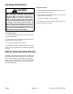
Safety Instructions The Groundsmaster 3280−D and 3320 meet or exceeds CEN standard EN 836:1997, ISO standard 5395:1990 (when appropriate decals applied), and ANSI B71.4−2004 specifications when weights are installed according to information in the Traction Unit Operator’s Manual.
7. Do not park on slopes unless wheels are chocked or blocked. Safety 6. Anytime the machine is parked (short or long term), the cutting deck (or implement) should be lowered to the ground. This relieves pressure from the lift circuit and eliminates the risk of the cutting deck (or implement) accidentally lowering to the ground. Maintenance and Service 1. Before servicing or making adjustments, lower cutting deck (or implement), stop engine, set parking brake and remove key from the switch. 11.
Jacking Instructions Rear End Jacking CAUTION 1. Set parking brake and chock both front tires to prevent the machine from moving. When changing attachments, tires or performing other service, use correct blocks, hoists and jacks. Make sure machine is parked on a solid level surface such as a concrete floor. Prior to raising machine, remove any attachments that may interfere with the safe and proper raising of the machine. Always chock or block wheels.
Chapter 2 Product Records and Maintenance PRODUCT RECORDS . . . . . . . . . . . . . . . . . . . . . . . . . MAINTENANCE . . . . . . . . . . . . . . . . . . . . . . . . . . . . . . EQUIVALENTS AND CONVERSIONS . . . . . . . . . . . Decimal and Millimeter Equivalents . . . . . . . . . . . . U.S. to Metric Conversions . . . . . . . . . . . . . . . . . . . TORQUE SPECIFICATIONS . . . . . . . . . . . . . . . . . . . Fastener Identification . . . . . . . . . . . . . . . . . . . . . . .
Equivalents and Conversions Product Records and Maintenance Page 2 − 2 Groundsmaster 3280−D/3320
Recommended fastener torque values are listed in the following tables. For critical applications, as determined by Toro, either the recommended torque or a torque that is unique to the application is clearly identified and specified in this Service Manual. These Torque Specifications for the installation and tightening of fasteners shall apply to all fasteners which do not have a specific requirement identified in this Service Manual.
Standard Torque for Dry, Zinc Plated and Steel Fasteners (Inch Series) Thread Size Grade 1, 5 & 8 with Thin Height Nuts SAE Grade 1 Bolts, Screws, Studs & Sems with Regular Height Nuts (SAE J995 Grade 2 or Stronger Nuts) in−lb in−lb N−cm 10 + 2 13 + 2 147 + 23 # 6 − 32 UNC # 6 − 40 UNF # 8 − 32 UNC 13 + 2 25 + 5 # 10 − 24 UNC 30 + 5 SAE Grade 8 Bolts, Screws, Studs & Sems with Regular Height Nuts (SAE J995 Grade 5 or Stronger Nuts) in−lb N−cm in−lb N−cm 15 + 2 169 + 23 23 + 3 262 + 34
Standard Torque for Dry, Zinc Plated and Steel Fasteners (Metric Series) Class 8.8 Bolts, Screws and Studs with Regular Height Nuts (Class 8 or Stronger Nuts) Class 10.9 Bolts, Screws and Studs with Regular Height Nuts (Class 10 or Stronger Nuts) M5 X 0.8 57 + 6 in−lb 644 + 68 N−cm 78 + 8 in−lb 881 + 90 N−cm M6 X 1.0 96 + 10 in−lb 1085 + 113 N−cm 133 + 14 in−lb 1503 + 158 N−cm M8 X 1.25 19 + 2 ft−lb 26 + 3 N−m 28 + 3 ft−lb 38 + 4 N−m M10 X 1.
Other Torque Specifications SAE Grade 8 Steel Set Screws Wheel Bolts and Lug Nuts Recommended Torque Thread Size Recommended Torque** Thread Size Square Head Hex Socket 1/4 − 20 UNC 140 + 20 in−lb 73 + 12 in−lb 5/16 − 18 UNC 215 + 35 in−lb 145 + 20 in−lb 3/8 − 16 UNC 35 + 10 ft−lb 18 + 3 ft−lb 1/2 − 13 UNC 75 + 15 ft−lb 50 + 10 ft−lb 7/16 − 20 UNF Grade 5 65 + 10 ft−lb 88 + 14 N−m 1/2 − 20 UNF Grade 5 80 + 10 ft−lb 108 + 14 N−m M12 X 1.25 Class 8.
Chapter 3 Gasoline Engine INTRODUCTION . . . . . . . . . . . . . . . . . . . . . . . . . . . . . . SPECIFICATIONS . . . . . . . . . . . . . . . . . . . . . . . . . . . . GENERAL INFORMATION . . . . . . . . . . . . . . . . . . . . . Adding Oil to Engine . . . . . . . . . . . . . . . . . . . . . . . . . ADJUSTMENTS . . . . . . . . . . . . . . . . . . . . . . . . . . . . . . Adjust Throttle Control . . . . . . . . . . . . . . . . . . . . . . . Adjust Choke Control . . . . . . . . . . . . . . . . . . . . . . .
Specifications Item Description Make / Designation Briggs & Stratton/Daihatsu, 4−stroke, Liquid Cooled, OHV, Gasoline Number of Cylinders 3 Bore x Stroke mm (in.) 72 x 78 (2.834 x 3.07) Total Displacement cc (cu. in.) 952 (58.1) Compression Ratio 8.6:1 Firing Order 1−2−3 Dry Weight (approximate) kg (lb.) 62 (137) Fuel Unleaded, regular grade (87 octane minimum) Carburetor Single barrel, float feed, 12 VDC shut−off solenoid Fuel Tank Capacity liter (U.S. gal.) 48.5 (12.
General Information Adding Oil to Engine Gasoline Engine When adding oil to the engine, maintain clearance between the oil fill device and the oil fill opening in the valve cover (Fig. 1). This clearance is necessary to allow venting when adding engine oil which will prevent oil from running into the breather tube and intake system.
Adjustments Adjust Throttle Control Proper throttle operation is dependent upon proper adjustment of throttle control. Make sure throttle control is operating properly. 2 3 1. Move remote throttle control lever to FAST position. 2. Check position of speed control lever on governor bracket. Speed control lever should be contacting high speed screw when throttle control lever is in FAST position. 3.
Adjust Engine Speed 1. Allow engine to reach operating temperature before checking or adjusting engine speed. Make sure that throttle control is adjusted properly before adjusting engine speed (see Adjust Throttle Control in this section). 2 3 2. Park machine on a level surface, lower cutting deck (or implement) and engage parking brake. Make sure that P.T.O. switch is OFF. Raise hood to gain access to engine controls. 1 3. With engine running, move remote throttle control lever to FAST position.
Service and Repairs Fuel System 5 6 4 26 7 3 8 2 9 1 27 28 25 16 12 29 21 10 30 19 20 13 24 12 11 17 19 13 18 23 22 15 12 14 19 15 16 RIGHT FRONT 32 31 Figure 6 1. 2. 3. 4. 5. 6. 7. 8. 9. 10. 11. Fuel tank Seat plate Flange head screw (2 used) Grommet Knob Bypass cover Threaded insert Flange nut (2 used) Radiator support Vent tube R−clamp Gasoline Engine 12. 13. 14. 15. 16. 17. 18. 19. 20. 21. 22.
9. Disconnect fuel hoses from standpipe (item 22) and elbow fitting (item 20) on the top of the fuel tank. DANGER 10.Remove fuel tank using Figure 6 as a guide. Because gasoline is highly flammable, use caution when storing or handling it. Do not smoke while filling the fuel tank. Do not fill fuel tank while engine is running, hot, or when machine is in an enclosed area. Always fill fuel tank outside and wipe up any spilled fuel before starting the engine.
Air Cleaner 10 11 1 9 2 3 4 5 5 8 RIGHT 7 FRONT 6 Figure 8 1. 2. 3. 4. Air cleaner assembly Flat washer (2 used) Lock nut Air inlet hose 5. 6. 7. 8. Hose clamp Cap screw (2 used) Lock washer (2 used) Spacer 9. Air inlet hose 10. Cap screw (2 used) 11. Mounting bracket Removal 2 1 1. Remove air cleaner components as needed using Figures 8 and 9 as guides. 2. See Traction Unit Operator’s Manual for air cleaner service procedures.
Gasoline Engine This page is intentionally blank.
Radiator 34 33 27 RIGHT 20 13 7 FRONT 21 22 26 19 23 25 28 24 29 5 18 30 3 31 1 2 8 32 17 3 16 13 4 6 14 9 15 11 9 12 10 3 Figure 10 1. 2. 3. 4. 5. 6. 7. 8. 9. 10. 11. 12. Radiator Hydraulic hose Screw (8 used) Radiator shield Intake cover Flange nut (8 used) Screen Radiator support Pop rivet (5 used) Backup washer (5 used) Draincock Vent hose Gasoline Engine 13. 14. 15. 16. 17. 18. 19. 20. 21. 22. 23.
Removal (Fig. 10) 1. Park machine on a level surface, lower cutting deck (or implement), stop engine, engage parking brake and remove key from the ignition switch. 9. Remove four (4) cap screws, flat washers and lock nuts that secure fan shroud to radiator. Position fan shroud away from the radiator. 10.Support the radiator assembly before loosening mounting fasteners. 2. Open hood (see Traction Unit Operator’s Manual). 11. Remove screws and flange nuts that secure radiator to radiator support.
Engine 7 10 5 8 6 9 5 4 50 to 60 ft−lb (68 to 81 N−m) 11 3 2 12 16 13 26 14 15 25 14 1 17 18 28 19 50 to 60 ft−lb (68 to 81 N−m) 24 26 25 RIGHT 20 24 FRONT 21 21 22 22 27 23 20 23 Figure 11 1. 2. 3. 4. 5. 6. 7. 8. 9. 10. Engine Muffler bracket Lock washer Negative battery cable Flat washer Cap screw Flange head screw Flange nut Muffler gasket Muffler 11. 12. 13. 14. 15. 16. 17. 18. 19.
5. Remove cap screws and flange nuts that secure battery base to brackets. Remove battery base from machine (Fig. 12). 1 5 +− 6 CAUTION 2 3 Do not open radiator cap or drain coolant if the radiator or engine is hot. Pressurized, hot coolant can escape and cause burns. Ethylene−glycol antifreeze is poisonous. Dispose of coolant properly, or store it in a properly labeled container away from children and pets. 4 Figure 12 1. Battery 2. Cap screw (3 used) 3. Battery base 4. Flange nut (3 used) 5.
15.Disconnect wire harness connectors from the following engine components: 5 NOTE: Label all electrical leads for reassembly purposes. 3 4 A. Alternator connector and stud. B. High temperature shut down switch and temperature sender located on the water pump housing. 4 3 6 C. Fuel solenoid on carburetor. D. Oil pressure switch located near the engine oil dipstick. 3 E. Ignition coils located on the right side of the engine. F.
12.Install air cleaner (see Air Cleaner Installation in this section). One person should operate lift or hoist while the other person guides the engine into the machine. IMPORTANT: Make sure not to damage the engine, fuel hoses, hydraulic lines, electrical harness or other parts while installing the engine. C. Lower engine to the machine frame. Make sure that the engine bracket holes are aligned with the holes in the engine shock mounts. D. Secure engine to the engine mounts. 7.
This page is intentionally blank.
Chapter 4 Diesel Engine Table of Contents INTRODUCTION . . . . . . . . . . . . . . . . . . . . . . . . . . . . . . SPECIFICATIONS . . . . . . . . . . . . . . . . . . . . . . . . . . . . ADJUSTMENTS . . . . . . . . . . . . . . . . . . . . . . . . . . . . . . Adjust Throttle Control . . . . . . . . . . . . . . . . . . . . . . . 1 2 3 3 SERVICE AND REPAIRS . . . . . . . . . . . . . . . . . . . . . . 4 Fuel System . . . . . . . . . . . . . . . . . . . . . . . . . . . . . . . . 4 Air Cleaner . . . . . . . . .
Specifications Item Description Make / Designation Kubota, 4−stroke, Liquid Cooled, OHV Diesel Number of Cylinders 3 Bore x Stroke mm (in.) 78 x 78.4 (3.07 x 3.09) Total Displacement cc (cu. in.) 1123 (68.53) Compression Ratio 22.0:1 Firing Order 1 (front) − 2 − 3 Dry Weight (approximate) kg (lb.) 93 (205) Fuel No. 2−D Diesel Fuel (ASTM D975) Fuel Injection Pump Bosch MD type mini Fuel Injector Nozzle Mini Nozzle (DNOPD) Fuel Tank Capacity liter (U.S. gal.) 48.5 (12.
Adjustments Adjust Throttle Control Proper throttle operation is dependent upon proper adjustment of throttle control. Make sure throttle control is operating properly. 2 3 1. Move remote throttle control lever to FAST position. 2. Check position of speed control lever on fuel injection pump. Speed control lever should be contacting high speed screw when throttle control lever is in FAST position. Figure 1 1. Throttle cable 2. High speed screw 3. Speed control lever Diesel Engine 3.
Service and Repairs Fuel System 5 6 4 26 7 3 8 9 2 10 30 21 1 11 11 25 12 20 31 16 32 20 19 11 24 13 33 19 12 17 12 18 23 15 22 11 16 14 15 19 29 28 16 27 RIGHT FRONT 35 34 Figure 2 1. 2. 3. 4. 5. 6. 7. 8. 9. 10. 11. 12. Fuel tank Seat plate Flange head screw (2 used) Grommet Knob Bypass cover Threaded insert Flange nut (2 used) Radiator support Vent tube Hose clamp Fuel hose (tank venting) Diesel Engine 13. 14. 15. 16. 17. 18. 19. 20. 21. 22. 23. 24.
9. Disconnect fuel hoses from standpipe (item 22) and elbow fittings (item 20) on the top of the fuel tank. DANGER 10.Remove fuel tank using Figure 2 as a guide. Because diesel fuel is highly flammable, use caution when storing or handling it. Do not smoke while filling the fuel tank. Do not fill fuel tank while engine is running, hot or when machine is in an enclosed area. Always fill fuel tank outside and wipe up any spilled diesel fuel before starting the engine.
Air Cleaner 8 5 7 1 2 6 3 4 5 5 RIGHT FRONT Figure 4 1. Air cleaner assembly 2. Flat washer (2 used) 3. Lock nut (2 used) 4. Intake air hose 5. Hose clamp 6. Air hose 7. Cap screw (2 used) 8. Air cleaner mount Removal 2 1 1. Park machine on a level surface, lower cutting deck (or implement), stop engine, engage parking brake and remove key from the ignition switch. Raise hood. 5 2. Remove air cleaner components as needed using Figures 4 and 5 as guides. 3.
Diesel Engine This page is intentionally blank.
Radiator 9 10 4 32 4 11 9 12 3 8 2 31 33 6 4 12 11 7 5 5 1 13 9 24 4 30 27 14 29 25 18 28 21 26 24 4 5 6 15 15 16 17 8 3 RIGHT 22 19 FRONT 20 23 21 Figure 6 1. 2. 3. 4. 5. 6. 7. 8. 9. 10. 11. Radiator/oil cooler assembly Radiator cap Hose clamp Flat washer Lock nut Hose clamp Upper radiator hose Foam seal Cap screw Coolant reservoir Hose 12. 13. 14. 15. 16. 17. 18. 19. 20. 21. 22.
3. Drain coolant from radiator. A. Slowly remove radiator cap from the radiator. B. Place drain pan below the radiator drain plug located on the bottom of the radiator. Loosen draincock and allow coolant to drain from radiator. 4. Remove screen from machine (see Traction Unit Operator’s Manual). 3. Carefully position radiator assembly to the radiator support. Secure radiator with six (6) flange head screws and flange nuts. 4. Position fan shroud to the radiator.
Engine 28 29 30 31 27 32 33 26 26 34 14 50 to 60 ft−lb (68 to 81 N−m) 13 25 + 35 − 24 21 38 22 37 20 15 16 14 13 19 18 39 1 12 17 36 5 23 41 40 11 50 to 60 ft−lb (68 to 81 N−m) 7 40 10 2 3 RIGHT 4 3 6 4 FRONT 5 8 9 6 Figure 8 1. 2. 3. 4. 5. 6. 7. 8. 9. 10. 11. 12. 13. 14.
Removal (Fig. 8) 4 6 3 2 4 2. Open hood (see Traction Unit Operator’s Manual). 6 4 7 1. Park machine on a level surface, lower cutting deck (or implement), stop engine and remove key from the ignition switch. Chock wheels to keep the machine from moving. 5 5 3. Disconnect negative (−) and then positive (+) battery cables at the battery. 8 1 4. Remove battery from machine (see Battery Service in the Service and Repairs section of Chapter 6 − Electrical System). CAUTION Figure 9 1. 2. 3. 4.
12.Disconnect hoses from engine: CAUTION A. Loosen clamps and disconnect upper and lower radiator hoses from the engine. B. At injector pump, loosen hose clamps and disconnect supply and return fuel hoses from the pump fittings (Fig. 10). Plug hoses to prevent leakage and contamination. 13.Disconnect transmission drive shaft from engine (see Hydraulic Transmission Drive Shaft Removal in the Service and Repairs section of Chapter 5 − Hydraulic System). 14.
8. Install clevis pin and cotter pin to secure hood cable to muffler bracket. 1. Locate machine on a level surface with cutting deck (or implement) lowered and key removed from the ignition switch. Chock wheels to keep the machine from moving. 2. Make sure that all parts removed from the engine during maintenance or rebuilding are reinstalled to the engine. 9.
18.Position battery base to brackets and secure with cap screws and flange nuts. 21.Connect positive (+) and then negative (−) battery cables to the battery. 19.Install battery to machine (see Battery Service in the Service and Repairs section of Chapter 6 − Electrical System). 22.Bleed fuel system (see Traction Unit Operator’s Manual). 23.Close hood (see Traction Unit Operator’s Manual). 20.Check engine oil level (see Traction Unit Operator’s Manual).
Chapter 5 Hydraulic System SPECIFICATIONS . . . . . . . . . . . . . . . . . . . . . . . . . . . . . 2 GENERAL INFORMATION . . . . . . . . . . . . . . . . . . . . . 3 Hydraulic Hoses . . . . . . . . . . . . . . . . . . . . . . . . . . . . 3 Hydraulic Fitting Installation . . . . . . . . . . . . . . . . . . . 3 Towing Traction Unit . . . . . . . . . . . . . . . . . . . . . . . . . 5 Check Hydraulic Fluid . . . . . . . . . . . . . . . . . . . . . . . 5 HYDRAULIC SCHEMATICS . . . . . . . . . . . . . . . . . .
Specifications Item Description Hydrostatic Transmission Sauer Danfoss (Sundstrand), U--type, Axial Piston Design, Model Series 15 .9 Cubic Inches (15 cc) .9 Cubic Inches (15 cc) Pump Maximum Displacement (per revolution) Motor Displacement (per revolution) Charge Pump Displacement (per revolution) Gerotor Pump in Hydrostat .3 Cubic Inches (4.9 cc) Implement (Lift/Steering) Relief Pressure 700 to 1000 PSI (48.2 to 69.
General Information Hydraulic Hoses Hydraulic hoses are subject to extreme conditions such as pressure differentials during operation and exposure to weather, sun, chemicals, very warm storage conditions or mishandling during operation and maintenance. These conditions can cause damage or premature deterioration. Some hoses are more susceptible to these conditions than others. Inspect the hoses frequently for signs of deterioration or damage.
SAE Straight Thread O--Ring Port -- Non--adjustable 1. Make sure both threads and sealing surfaces are free of burrs, nicks, scratches or any foreign material. 2. Always replace the o--ring seal when this type of fitting shows signs of leakage. O--Ring 3. Lubricate the o--ring with a light coating of oil. 4. Install the fitting into the port and tighten it down full length until finger tight. Figure 3 5. Tighten the fitting to the correct Flats From Finger Tight (F.F.F.T.). Size 4 (1/4 in.
Towing Traction Unit IMPORTANT: If towing limits are exceeded, severe damage to the transmission may occur. If it becomes necessary to tow (or push) the machine, tow (or push) at a speed below 3 mph (4.8 kph), and for a very short distance. If machine needs to be moved a considerable distance, machine should be transported on a trailer. The transmission is equipped with two check valves that need to be pressed for towing or pushing (Fig. 6). See Traction Unit Operator’s Manual for Towing Procedures.
HYDROSTATIC TRANSMISSION & CHARGE PUMP Hydraulic System STEERING VALVE 700 -- 1000 PSI Page 5 -- 6 Rev. A L E T STEERING CYLINDER R P .3 CU IN/REV 3.
Groundsmaster 3280--D/3320 Page 5 -- 7 Rev.
HYDROSTATIC TRANSMISSION & CHARGE PUMP Hydraulic System STEERING VALVE 700 -- 1000 PSI Figure 8 Page 5 -- 8 Rev. A L E T STEERING CYLINDER R P .3 CU IN/REV 3.
Traction Circuit Reverse Direction The hydrostatic transmission input shaft is rotated by a drive shaft off the front of the engine crankshaft. Pushing the top of the traction pedal rotates the variable displacement pump swash plate in the transmission to create a flow of oil. This oil is directed to the fixed displacement motor in the transmission which turns the front axle input shaft to drive the front wheels in the forward direction.
Figure 9 Hydraulic System Page 5 -- 10 Rev. A Groundsmaster 3280--D/3320 HYDROSTATIC TRANSMISSION & CHARGE PUMP STEERING VALVE 700 -- 1000 PSI L E T STEERING CYLINDER R P .3 CU IN/REV 3.
Lift Circuit During conditions of not steering or raising/lowering the cutting deck (or implement), flow from the charge pump goes to the lift control valve and is by--passed through the oil cooler and then to the reservoir (front axle). Raise Cutting Deck (Or Implement) (Fig. 9) When the cutting deck (or implement) is to be raised, the control valve spool is positioned back and flow is directed out the B port of the control valve to the cylinder (upper) end of the lift cylinders.
Steering Circuit The charge pump in the hydrostat supplies flow for the steering circuit and for the cutting deck (or implement) lift circuit. Pump output flows to the steering control valve before reaching the lift valve so the steering circuit has priority. Steering circuit pressure is limited from 700 to 1000 PSI by the implement relief valve located in the hydrostat. out the L port. Pressure retracts the steering cylinder for a left turn.
Hydraulic System This page is intentionally blank.
Special Tools Order these tools from your Toro Distributor. Hydraulic Pressure Test Kit Toro Part Number: TOR47009 Use to take various pressure readings for diagnostic tests. Quick disconnect fittings provided attach directly to mating fittings on machine test ports without tools. A high pressure hose is provided for remote readings. Contains one each: 1000 PSI (70 Bar), 5000 PSI (350 Bar) and 10000 PSI (700 Bar) gauges. Use gauges as recommended in Testing section of this chapter.
Hydraulic Test Fitting Kit Toro Part Number: TOR4079 This kit includes a variety of o--ring Face Seal fittings to enable connection of test gauges to the system. The kit includes: tee’s, unions, reducers, plugs, caps, and male test fittings. Figure 14 O--Ring Kit Toro Part Number: 16--3799 Hydraulic System The kit includes o--rings in a variety of sizes for face seal and port seal hydraulic connections. It is recommended that o--rings be replaced whenever a hydraulic connection is loosened.
Troubleshooting The cause of an improperly functioning hydraulic system is best diagnosed with the use of proper testing equipment and a thorough understanding of the complete hydraulic system. A hydraulic system with an excessive increase in heat or noise has a potential for failure. Should either of these conditions be noticed, immediately stop the machine, turn off the engine, locate the cause of the trouble, and correct it before allowing the machine to be used again.
Problem Possible Cause Traction response is sluggish Charge pressure is low. Hydraulic oil is very cold. Hydrostat check valve is not seating or is damaged. Brakes are not released. Hydrostat is worn or damaged. No traction in either direction Brakes are not released. Oil level in reservoir (front axle) is low. Hydrostat check valve is not seating or is damaged. Charge pressure is low. Transmission drive shaft or key damaged (steering and lift circuits affected as well). Hydrostat is worn or damaged.
Problem Possible Cause Cutting deck (or implement) raises, but will not stay up Lift cylinder leaks internally. Steering inoperative or sluggish Engine speed is too low. Lift control valve leaks. Reservoir (front axle) oil level is low. Steering components (e.g. tie rods, steering cylinder ends) worn or binding. Steering cylinder is binding. Implement relief valve stuck or damaged (Note: lift circuit also affected). Steering control valve is worn or damaged. Steering cylinder leaks internally.
Testing The most effective method for isolating problems in the hydraulic system is by using hydraulic test equipment such as pressure gauges and flow meters in the circuits during various operational checks (See Special Tools section in this Chapter). 2. Put caps or plugs on any hydraulic lines left open or exposed during testing or removal of components.
Charge Pressure Test (Using Pressure Gauge) A charge pressure test should be performed to identify if a worn or damaged hydrostatic transmission is causing a hydraulic system problem. NOTE: Before conducting charge pressure test, determine counterbalance pressure setting for the machine (see Traction Unit Operator’s Manual). 11. The pressure should drop no more than 15% from initial test reading (Step 8 above). A pressure drop of more than 15% may indicate a traction circuit leak (e.g.
Implement Relief Pressure Test (Using Pressure Gauge) The implement relief pressure test should be done if a problem is suspected with the implement relief valve. 3 4 NOTE: When conducting the Implement Relief Pressure Test, use a 5000 PSI (350 Bar) Pressure Gauge. 1. Perform steps 1 through 8 of the Charge Pressure Test (see Test No. 1 in this section). Make sure to use a 5000 PSI (350 Bar) Pressure Gauge. 2 1 Figure 18 1. Seat base opening 2. Check valve 3. Pipe plug 4. Implement relief valve 3.
Lift Cylinder Internal Leakage Test LOOK FOR LEAKAGE HYDROSTATIC TRANSMISSION & CHARGE PUMP 700 -- 1000 PSI LIFT CYLINDERS (FULLY EXTENDED) TEST PORT P OIL COOLER STEERING VALVE P E T LIFT VALVE B T LIFT LEVER PULLED TO RAISE R L STEERING CYLINDER Working Pressure Low Pressure (Charge) Return or Suction Flow Figure 20 Hydraulic System Page 5 -- 22 Rev.
Procedure for Lift Cylinder Internal Leakage Test: The lift cylinder internal leakage test should be performed if a cutting deck (or implement) raise and lower problem is identified. This test will determine if the lift cylinders are faulty. 11. After testing is completed, remove the support from the cutting deck (or implement). Start engine and operate lift cylinders through several up and down cycles. Stop the engine and check for any leakage. 12.Check hydraulic oil level in reservoir (front axle).
Steering Cylinder Internal Leakage Test FROM HYDROSTAT STEERING VALVE P R TO RESERVOIR E T STEERING WHEEL TURNED FOR RIGHT TURN L LOOK FOR LEAKAGE STEERING CYLINDER (FULLY EXTENDED) Figure 22 Hydraulic System Page 5 -- 24 Groundsmaster 3280--D/3320
Procedure for Steering Cylinder Internal Leakage Test: 4. Turn the steering wheel for a right turn (clockwise) so the steering cylinder rod is fully extended. The steering cylinder internal leakage test should be performed if a steering problem is identified. This test will determine if the steering cylinder is faulty. 5. Remove hydraulic hose from the fitting on the rod end of the steering cylinder. Plug the end of the hose.
Charge Pump Flow Test (Using Tester With Pressure Gauges and Flow Meter) The charge pump flow test should be performed if a hydraulic problem is identified that affects both the steering and lift circuits. NOTE: The charge pump provides make--up oil for internal hydrostat components before flow is available for the steering and lift circuits. Flow measured in this test will be less than total charge pump output. 1.
Adjustments Traction Pedal Friction Wheel The traction pedal friction wheel is designed to reduce transmission oscillation caused by rapid back and forth foot movements against the traction pedal. This is most noticeable when operating over bumpy terrain. 1 3 Occasionally inspect the friction wheel surface that contacts the traction pedal (Fig. 24). If the friction wheel is worn flat at this point, the wheel should be rotated to restore contact with the pedal. Adjustment (Fig. 25) 2 1.
Service and Repairs General Precautions for Removing and Installing Hydraulic System Components Before Repair or Replacement of Components After Repair or Replacement of Components 1. Before removing any parts from the hydraulic system, park machine on a level surface, engage parking brake, lower cutting deck (or implement) and stop engine. Remove key from the ignition switch. 1.
Flush Hydraulic System IMPORTANT: Flush the hydraulic system any time there is a severe component failure or the system is contaminated (oil appears milky or black or contains metal particles). 8. Make sure traction pedal is in neutral and the P.T.O. switch is off. Turn ignition key switch to start; engage starter for ten (10) seconds to prime hydraulic pump. Repeat this step again. 1. Park machine on a level surface.
Hydraulic System Start--up NOTE: When initially starting the hydraulic system with new or rebuilt components such as pumps or lift cylinders, it is important that this start--up procedure be used. This procedure reduces the chance of damaging the system or its components from not purging the system of air. 1. After the hydraulic system components have been properly installed and if the hydrostatic transmission was rebuilt or replaced, make sure hydrostat housing is at least half full of clean hydraulic oil.
Hydraulic System This page is intentionally blank.
Transmission Drive Shaft RIGHT FRONT 80 to 100 in--lb (9.0 to 11.3 N--m) 8 3 13 Loctite #242 12 2 6 5 4 7 5 6 4 2 2 1 3 8 10 9 11 Figure 26 1. 2. 3. 4. 5. Drive shaft Conelock nut Flat washer Rubber coupling Coupling spacer 6. 7. 8. 9. Cap screw Square head screw (2 used) Coupling spacer Pump hub Removal (Fig. 26) 1. Park the machine on a level surface, engage parking brake, lower cutting deck (or implement) and stop engine. Remove key from the ignition switch. 2.
3. Loosen square head screws (item 7) that secure pump hub to transmission input shaft. Slide pump hub toward engine, align holes in pump hub with drive shaft flanges and place cap screws in holes. 4. Rotate drive shaft to check alignment of the drive shaft in all positions. Drive shaft and hub must be aligned within .125” (3 mm). 5. If alignment adjustment is needed, loosen lock nut and jam nut that secure transmission anchor (Fig. 27).
Hydrostatic Transmission 24 RIGHT 21 20 FRONT 33 23 19 14 50 34 36 29 28 28 47 16 8 34 1 7 10 6 13 41 32 37 17 9 39 31 18 15 37 32 25 30 31 26 27 22 40 38 35 49 4 5 3 2 45 28 46 42 43 48 Loctite #242 44 43 12 11 Figure 28 1. 2. 3. 4. 5. 6. 7. 8. 9. 10. 11. 12. 13. 14. 15. 16. 17.
1. Park the machine on a level surface, engage parking brake, lower cutting deck (or implement) and stop engine. Remove key from the ignition switch. 2. To prevent contamination of the hydraulic system, thoroughly clean transmission and front axle. CAUTION Operate all hydraulic controls to relieve system pressure and avoid injury from pressurized hydraulic oil. 3. Label hydraulic hoses to assist in assembly. Disconnect all hydraulic hoses from the transmission assembly.
8. Slide traction rod (item 50) to pump lever and secure with flat washer (item 20) and cotter pin (item 19). 11. Install hydraulic hoses to fittings on transmission in positions noted during disassembly. 9. Check transmission drive shaft alignment and adjust if necessary (see Transmission Drive Shaft in this section). Install transmission drive shaft. 12.Check hydraulic fluid level in reservoir (front axle) and adjust as required (see Traction Unit Operator’s Manual). 10.
Hydraulic System This page is intentionally blank.
Hydrostatic Transmission Service 7 9 4 5 1 48 3 13 2 14 15 10 19 11 8 24 16 26 31 14 33 27 36 12 6 25 32 5 7 23 22 20 49 17 47 46 40 46 48 40 29 18 40 30 21 34 50 15 18 54 35 53 24 52 23 45 44 39 37 41 56 51 42 38 57 28 55 43 Figure 29 1. 2. 3. 4. 5. 6. 7. 8. 9. 10. 11. 12. 13. 14. 15. 16. 17. 18. 19.
Hydrostatic Transmission Neutral Arm Assembly 28 to 36 in--lb (3.3 to 4.1 N--m) 18 16 17 15 71 to 89 in--lb (8 to 10 N--m) 14 71 to 89 in--lb (8 to 10 N--m) 11 13 12 9 1 2 10 9 3 8 15 to 17 ft--lb (20 to 24 N--m) 4 7 5 6 Transmission housing Cap screw Mounting plate Neutral return spring Neutral return arm Bushing 7. 8. 9. 10. 11. 12. Grease fitting Eccentric pin Retaining ring Jam nut Socket head screw Pin Disassembly (Fig. 30) 1.
Lift Cylinder 20 4 5 3 6 7 1 11 8 9 13 15 12 5 3 10 16 14 2 17 7 1 8 19 9 10 18 RIGHT FRONT Figure 32 1. 2. 3. 4. 5. 6. 7. Lift cylinder Cap screw O--ring Hydraulic fitting O--ring Hydraulic hose Hose clamp 8. 9. 10. 11. 12. 13. 14. Hose stem Cotter pin Cylinder pin Hydraulic hose Hydraulic hose Hydraulic tee fitting Hydraulic hose 15. 16. 17. 18. 19. 20.
Removal (Fig. 32) Installation (Fig. 32) 1. Park the machine on a level surface, engage the parking brake, lower the cutting deck (or implement) and stop the engine. Remove the key from the ignition switch. 1. Coat new o--rings lightly with clean hydraulic oil. Install hydraulic fittings with new o--rings to the lift cylinder. 2. Read the General Precautions for Removing and Installing Hydraulic System Components at the beginning of the Service and Repairs section of this chapter. 2.
Steering Control Valve 32 30 24 23 25 26 17 27 31 20 to 26 ft--lb (27.1 to 35.3 N--m) 29 14 28 22 21 20 19 14 18 17 16 12 33 13 15 14 3 11 34 1 35 2 RIGHT FRONT 10 9 5 8 7 4 6 Figure 33 1. 2. 3. 4. 5. 6. 7. 8. 9. 10. 11. 12. Tower panel Phillips head screw (6 used) Nut retainer (6 used) Flange head screw Sleeve protector Hydraulic hose Hydraulic hose Hydraulic hose Hydraulic hose Hydraulic hose Tilt steering lever Grip Hydraulic System 13. 14. 15. 16. 17. 18. 19. 20. 21. 22.
Removal (Fig. 33) Installation (Fig. 33) 1. Park the machine on a level surface, engage the parking brake, lower the cutting deck (or implement) and stop the engine. Remove the key from the ignition switch. 1. Slide steering control valve onto steering column. Secure steering control valve to steering column with four (4) socket head screws (item 20) and spring washers (item 19). 2. Remove knob from end of parking brake rod. 2. Remove caps and plugs from disconnected hoses and fittings. 3.
Steering Control Valve Service 8 9 7 6 10 5 4 3 2 11 1 12 22 13 14 15 21 13 16 20 13 17 18 20 to 24 ft--lb (27 to 33 N--m) 19 Figure 35 1. 2. 3. 4. 5. 6. 7. 8. Sleeve Cross pin Ring Spool Bearing assembly Shaft seal Ball stop Ball 9. 10. 11. 12. 13. 14. 15. Dust seal ring Housing Cardan shaft Spacer O--ring Distribution plate Inner gearwheel 16. 17. 18. 19. 20. 21. 22.
Hydraulic System This page is intentionally blank.
Steering Cylinder (2 Wheel Drive) 2 3 4 1 5 2 6 13 130 to 150 ft--lb (176 to 203 N--m) 4 7 8 12 9 10 RIGHT 11 FRONT 130 to 150 ft--lb (176 to 203 N--m) Figure 36 1. 2. 3. 4. 5. Steering cylinder O--ring 45o hydraulic fitting O--ring Hydraulic fitting Hydraulic System 6. 7. 8. 9. Cap screw Lock nut Rear axle (2WD) Washer Page 5 -- 46 10. 11. 12. 13.
Removal (Fig. 36) 1. Park the machine on a level surface, engage the parking brake, lower the cutting deck (or implement) and stop the engine. Remove the key from the ignition switch. 2. Read the General Precautions for Removing and Installing Hydraulic System Components at the beginning of the Service and Repairs section of this chapter. 2. Position steering cylinder to machine. Make sure to place spacer ring (item 13) and washer (item 9) in locations noted during removal (Fig. 37). 3.
Steering Cylinder Service (2 Wheel Drive) 3 5 6 1 9 2 10 12 4 7 8 11 13 Figure 38 1. 2. 3. 4. 5. Grease fitting Piston rod Wiper Gland Seal 6. 7. 8. 9. O--ring O--ring Piston Seal 10. 11. 12. 13. Disassembly (Fig. 38) 1. Remove oil from cylinder into a drain pan by slowly pumping the cylinder shaft. Plug both ports and clean the outside of cylinder. IMPORTANT: Prevent damage when clamping the steering cylinder into a vise; clamp on the pivot end only.
3. Inspect head, piston rod and piston for excessive pitting, scoring and wear. Replace any worn or damaged parts. Assembly (Fig. 38) 1. Coat new seals, wiper and all o--rings lightly with hydraulic oil. Install new seal and o--rings to the piston. Install wiper, o--ring and seal to the gland. IMPORTANT: Do not clamp vise jaws against piston rod surface. Protect rod surface before mounting in vise. 2. Mount rod securely in a vise. 5. Remove shaft from vise.
Steering Cylinder (4 Wheel Drive) 9 10 70 to 90 ft--lb (95 to 122 N--m) 11 8 5 6 4 12 4 7 37 to 42 ft--lb (50 to 57 N--m) 3 20 2 21 14 12 13 1 13 18 15 16 18 17 RIGHT FRONT 19 Figure 39 1. 2. 3. 4. 5. 6. 7. Steering cylinder O--ring 90o hydraulic fitting O--ring Hydraulic hose Hydraulic hose 45o hydraulic fitting Hydraulic System 8. 9. 10. 11. 12. 13. 14. Grease fitting Washer head screw Rear axle pin Grease fitting Retaining ring Ball joint Grease fitting Page 5 -- 50 15. 16.
Removal (Fig. 39) Installation (Fig. 39) 1. Park the machine on a level surface, engage the parking brake, lower the cutting deck (or implement) and stop the engine. Remove the key from the ignition switch. 1. Coat new o--rings lightly with clean hydraulic oil. If removed, install hydraulic fittings with new o--rings to the steering cylinder. Make sure to position fittings correctly in cylinder. 2.
Steering Cylinder Service (4 Wheel Drive) 1 5 7 10 2 11 3 12 6 4 8 9 Figure 40 1. 2. 3. 4. Internal collar Dust seal Backup washer O--ring 5. 6. 7. 8. Head Rod seal Shaft O--ring 9. 10. 11. 12. Disassembly (Fig. 40) 1. Remove oil from cylinder into a drain pan by slowly pumping the cylinder shaft. Plug both ports and clean the outside of cylinder. IMPORTANT: Prevent damage when clamping the steering cylinder into a vise; clamp on the pivot end only. Do not close vise enough to distort the barrel.
Assembly (Fig. 40) 5. Remove shaft from vise. 1. Coat new dust seal, uni--ring, backup washer, rod seal and all o--rings lightly with hydraulic oil. Install new o--ring and uni--ring to the piston. Install dust seal, backup washer, o--ring and rod seal to the head. IMPORTANT: Prevent damage when clamping the barrel into a vise; clamp on the pivot end only. Do not close vise enough to distort barrel. IMPORTANT: Do not clamp vise jaws against shaft surface. Protect shaft surface before mounting in vise.
Lift Control Valve 1 21 4 22 2 3 4 5 4 6 2 7 8 20 2 3 4 9 13 19 14 18 10 12 11 15 16 RIGHT FRONT 17 Figure 41 1. 2. 3. 4. 5. 6. 7. 8. Lift control valve O--ring Hydraulic adapter O--ring Hydraulic hose Hydraulic hose Hydraulic fitting O--ring 9. 10. 11. 12. 13. 14. 15. Hydraulic hose Flat washer (2 used) Cap screw (2 used) Lock washer (2 used) Pin Cotter pin Lift lever 16. 17. 18. 19. 20. 21. 22.
Removal (Figs. 41 and 42) 1. Park the machine on a level surface, engage the parking brake, lower the cutting deck (or implement) and stop the engine. Remove the key from the ignition switch. 5. Connect hydraulic hoses to hydraulic fittings on lift control valve. 6. Install fuel tank to machine (see Fuel Tank Installation in Chapter 3 -- Gasoline Engine or Chapter 4 -- Diesel Engine). 2.
Lift Control Valve Service 18 to 20 ft--lb (24 to 27 N--m) Loctite #242 10 to 15 ft--lb (14 to 20 N--m) 35 to 40 ft--lb (47 to 54 N--m) 18 to 20 ft--lb (24 to 27 N--m) Loctite #242 35 to 40 ft--lb (47 to 54 N--m) 16 21 24 25 1 17 2 19 18 24 to 36 in--lb (2.7 to 4.1 N--m) Loctite #242 22 23 15 11 10 14 9 7 5 12 8 4 4 6 20 3 13 Figure 43 1. 2. 3. 4. 5. 6. 7. 8. 9. Detent ball Spring Gasket O--ring Screw Washer Screw and lock washer (2 used) Spool Plug 10. 11. 12. 13. 14. 15. 16.
10.If control valve is equipped with counterbalance valve (Fig. 44), remove valve from control valve if needed. Counterbalance valve disassembly is not recommended. Inspection 1. Inspect spool and spool bore for wear. If wear is excessive, replace lift control valve assembly. 2. Inspect all springs and replace if damaged or broken. 3. Inspect detent plunger, detent ball and poppet for wear. Replace as necessary. 4. Inspect lockout seats for wear or damage. Replace as necessary. 5.
Counterbalance Valve Manifold (If Equipped) 10 RIGHT 6 11 5 FRONT 3 7 2 4 4 1 2 4 4 2 9 5 2 8 Figure 45 1. 2. 3. 4. Lift control valve Hydraulic adapter Hydraulic tube O--Ring 5. 6. 7. 8. O--Ring Counterbalance manifold Cap screw (2 used) Hydraulic hose NOTE: The counterbalance valve manifold is used on Groundsmaster 3280--D machines with serial numbers above 270000401 and Groundsmaster 3320 machines with serial numbers above 280000000. Removal (Fig. 45) 1.
Manifold Service (Fig. 46) 1. Make sure the manifold is thoroughly cleaned before removing either of the valves. IMPORTANT: Use care when handling the hydraulic valve. Slight bending or distortion of the stem tube can cause binding and malfunction. 2. Using a deep socket, remove valves from manifold. Note correct location of o--rings, sealing rings and backup rings. Remove and discard seal kit from valves. 3.
Oil Cooler (Groundsmaster 3280--D) 3 4 2 1 5 2 6 3 5 7 8 9 10 11 RIGHT FRONT Figure 47 1. 2. 3. 4. Radiator Lock washer Hex nut Oil cooler 5. 6. 7. 8. O--ring Hydraulic hose Hydraulic hose Flange head screw 9. Radiator support 10. Flange nut 11. Radiator shield Removal (Fig. 47) Installation (Fig. 47) 1. Park machine on a level surface, lower cutting deck (or implement), stop engine, engage parking brake and remove key from the ignition switch. 1.
Chapter 6 Electrical System Table of Contents ELECTRICAL DIAGRAMS . . . . . . . . . . . . . . . . . . . . . 1 SPECIAL TOOLS . . . . . . . . . . . . . . . . . . . . . . . . . . . . . 2 TROUBLESHOOTING . . . . . . . . . . . . . . . . . . . . . . . . . 4 Starting Problems . . . . . . . . . . . . . . . . . . . . . . . . . . . 4 General Run and Operating Problems . . . . . . . . . 6 ELECTRICAL SYSTEM QUICK CHECKS . . . . . . . . 8 Battery Test (Open Circuit Test) . . . . . . . . . . . . . . .
Special Tools Order special tools from your Toro Distributor. Some tools may also be available from a local supplier. Multimeter The multimeter can test electrical components and circuits for current, resistance, or voltage. Obtain this tool locally. NOTE: Toro recommends the use of a DIGITAL Volt− Ohm−Amp multimeter when testing electrical circuits. The high impedance (internal resistance) of a digital meter in the voltage mode will make sure that excess current is not allowed through the meter.
Battery Hydrometer Use the Battery Hydrometer when measuring specific gravity of battery electrolyte. Obtain this tool locally.
Troubleshooting For effective troubleshooting and repairs, you must have a good understanding of the electrical circuits and components used on this machine (see Chapter 8 − Electrical Diagrams). CAUTION Remove all jewelry, especially rings and watches, before doing any electrical troubleshooting or testing. Disconnect the battery cables unless the test requires battery voltage. If the machine has any interlock switches by−passed, they must be reconnected for proper troubleshooting and safety.
Starting Problems (continued) Problem Possible Causes Nothing happens when start attempt is made (either seat switch OR parking brake must be engaged for successful start). PTO switch is ON (pulled out) or is faulty. Traction pedal is not in neutral position. Interlock system has problem. Battery cables are loose or corroded. Battery ground to frame is loose or corroded. Battery is dead. Engine fuse (15 amp) is open. Fusible link is open.
General Run and Operating Problems Problem Possible Causes Engine continues to run (but should not) when the traction pedal is depressed with no operator on the seat. Seat switch is faulty. Seat switch wiring is loose, corroded or damaged. Traction neutral switch is out of adjustment or faulty. Engine kills when the traction pedal is depressed or the P.T.O. switch is pulled ON with the operator in the seat. Operator is lifting off the seat (seat switch not depressed fully). Parking brake is on.
General Run and Operating Problems (continued) Problem Possible Causes Engine Continues to run (but should not) when the PTO switch is ON with no operator in the seat. Seat switch is faulty. Seat switch wiring is loose, corroded or damaged. Traction neutral switch is out of adjustment or faulty. P.T.O. clutch does not engage. System fuse F1 (15 amp) or F3 (10 amp) is open. Logic power fuse F4 (2 amp) is open. Fuse block is faulty. P.T.O. switch is faulty. P.T.O. latch relay is faulty.
Electrical System Quick Checks Battery Test (Open Circuit Test) Use a multimeter to measure the battery voltage. Voltage Measured Battery Charge Level Set the multimeter to the DC volts setting. The battery should be at a temperature of 60o to 100o F (16o to 38o C). The ignition key should be in the OFF position and all accessories turned off. Connect the positive (+) multimeter lead to the positive battery post and the negative (−) multimeter lead to the negative battery post.
Check Operation of Interlock Switches CAUTION Electrical System Do not disconnect interlock switches. They are for the operator’s protection. Check the operation of the interlock switches daily for proper operation. Replace any malfunctioning switches before operating the machine. Interlock switch operation is described in the Traction Unit Operator’s Manual. The Groundsmaster 3280−D and Groundsmaster 3320 are equipped with a Standard Control Module which monitors interlock switch operation.
Component Testing For accurate resistance and/or continuity checks, electrically disconnect the component being tested from the circuit (e.g. unplug the ignition switch connector before doing a continuity check). NOTE: See the Kubota Workshop Manual: 05 Series Engine (Groundsmaster 3280−D) or Briggs & Stratton/ Daihatsu Engine Repair Manual (Groundsmaster 3320) for additional electrical component repair information.
Indicator Lights Charge Indicator Light 3 The charge indicator light should come on when the ignition switch is in the ON position with the engine not running. Also, it should illuminate with an improperly operating charging circuit while the engine is running. 2 Engine Oil Pressure Light 4 The engine oil pressure light should come on when the ignition switch is in the ON position with the engine not running.
Hour Meter 1. Connect the positive (+) terminal of a 12 VDC source to the positive (+) terminal of the hour meter. Hobbs 2. Connect the negative (−) terminal of the voltage source to the other terminal of the hour meter. QUARTZ 00001 HOURS 3. The hour meter should move a 1/10 of an hour in six minutes. 1 10 + 4. Disconnect the voltage source from the hour meter. BACK Figure 8 P.T.O. Switch The P.T.O. switch is mounted on the control panel and is pulled to engage the P.T.O. electric clutch.
Temperature Sender The temperature sender is attached to the water pump housing on the engine. There is a yellow wire attached to the temperature sender. If the ignition switch is in the ON position and the temperature sender has reduced resistance due to high coolant temperature, the High Temperature Warning indicator light on the console and the Over Temperature Warning input LED on the Standard Control Module should be illuminated. Testing 4. Install sender to the engine housing. A.
High Temperature Shutdown Switch The high temperature shutdown switch is located on the water pump housing. There is a blue/white wire attached to the shutdown switch. The Standard Control Module monitors the operation of the high temperature shutdown switch. If the ignition switch is in the ON position and the high temperature shutdown switch has closed due to excessive coolant temperature, the Module Over Temperature Shutdown input LED should be illuminated and the engine should shut down. Testing 6.
Oil Pressure Switch The engine oil pressure switch is located on the engine near the oil filter (Figs.17 and 18). The oil pressure switch is a normally closed switch that opens with pressure. On the Groundsmaster 3280−D (diesel engine), the oil pressure switch should open at approximately 8 PSI (0.56 kg/cm2). On the Groundsmaster 3320 (gasoline engine), the oil pressure switch should open between 2.9 to 5.7 PSI (0.2 to 0.4 kg/cm2).
Standard Control Module The Groundsmaster 3280−D and Groundsmaster 3320 are equipped with a Standard Control Module to monitor and control electrical components required for safe operation. This Module is located under the control panel (Fig. 19). Inputs from the ignition, neutral, parking brake, P.T.O., seat, temperature sender and high temperature shutdown switches are monitored by the Module. Current output to the P.T.O.
Traction Neutral Switch The traction neutral switch is a normally open proximity switch that closes when the traction pedal is in the neutral position. A socket head screw threaded into the hydrostat neutral return arm acts as the sensing plate for the switch. 2 The Standard Control Module monitors the operation of the traction neutral switch. If the ignition switch is in the ON position and the traction pedal is in the neutral position, the Module Neutral input LED should be illuminated. 1 Testing 1.
Seat Switch The seat switch is normally open and closes when the operator is on the seat. If the traction system or P.T.O. switch is engaged when the operator raises out of the seat, the engine will stop. The seat switch (Fig. 23) and its electrical connector are located directly under the seat. Testing of the switch can be done without seat removal by disconnecting the seat wire from the machine wiring harness. 1 The Standard Control Module monitors the operation of the seat switch.
Parking Brake Switch The switch used for the parking brake is a normally open switch. The switch closes when the parking brake is disengaged. The parking brake switch is located under the steering tower cover (Fig. 24). 6 1 2 5 The Standard Control Module monitors the operation of the parking brake switch. If the ignition switch is in the ON position and the parking brake is disengaged, the Module Parking Brake Off input LED should be illuminated. 3 4 Testing 1. Make sure the engine is off.
P.T.O. Electric Clutch An electric clutch is used to engage the P.T.O. The electric clutch is mounted on the engine crankshaft and engages when current is applied to the clutch. The clutch also incorporates a magnetic brake to stop clutch rotation when the clutch is de−energized. 3 1 Testing 1. Park machine on a level surface, lower cutting deck (or implement), stop engine, engage parking brake and remove key from the ignition switch. Raise hood. 2. Locate electric clutch on engine crankshaft (Fig. 25).
Fuses The fuse block is located under the control panel (Fig. 26). 1 Identification and Function The fuses are held in the fuse block. Use Figure 27 to identify each individual fuse and its correct amperage. Each fuse holder has the following function. Fuse 1 (15 Amp): Protects main power circuit to ignition switch terminal B Fuse 2 (10 Amp): Protects power circuit from ignition switch terminal S. Figure 26 1. Fuse block Fuse 3 (10 Amp): Protects power circuit from ignition switch terminal I.
Fuel Stop Solenoid (Groundsmaster 3280−D) The fuel stop solenoid used on the Groundsmaster 3280−D (diesel engine) must be energized for the diesel engine to run. The solenoid is mounted to the injection pump on the engine (Fig. 30). 2 In Place Testing NOTE: Prior to taking small resistance readings with a digital multimeter, short the test leads together. The meter will display a small resistance value (usually 0.5 ohms or less).
Glow Controller (Groundsmaster 3280−D) The glow controller used on the Groundsmaster 3280−D (diesel engine) is located under the control panel. 5. If any of the conditions in Step 3 are not met or power to terminal 1 exists and any of the other conditions in Step 4 are not met: NOTE: Refer to Chapter 11 − Electrical Diagrams when troubleshooting the glow controller circuit. A. Verify continuity of the circuitry from the battery to the glow relay and glow plugs (see Chapter 11 − Electrical Diagrams).
Glow Relay (Groundsmaster 3280−D) The glow relay used on the Groundsmaster 3280−D (diesel engine) is attached to the support bracket inside the right side frame near the fuel/water filter (Fig. 33). When energized, the glow relay allows electrical current to the engine glow plugs. 2 Testing NOTE: Prior to taking small resistance readings with a digital multimeter, short the meter test leads together. The meter will display a small resistance value (usually 0.5 ohms or less).
Fuel Pump (Groundsmaster 3280−D) The fuel pump used on the Groundsmaster 3280−D (diesel engine) is attached to the support bracket inside the right side frame near the fuel/water filter (Fig. 35). 4 3 IMPORTANT: When testing fuel pump, make sure that pump is not operated without fuel. DANGER 5 Because diesel fuel is highly flammable, use caution when handling it. Do not smoke while testing the fuel pump. Do not test fuel pump while engine is hot.
Fuel Pump (Groundsmaster 3320) The fuel pump used on the Groundsmaster 3320 (gasoline engine) is attached to the support bracket inside the right side frame near the fuel filter (Fig. 36). IMPORTANT: When testing fuel pump, make sure that pump is not operated without fuel. 5 4 DANGER 2 Because gasoline is highly flammable, use caution when handling it. Do not smoke while testing the fuel pump. Do not test fuel pump while engine is hot. Make sure that there is adequate ventilation when testing.
Fuel Pump Relay (Groundsmaster 3320) The Groundsmaster 3320 uses a relay to energize the fuel pump. The fuel pump relay is attached to the support bracket inside the right side frame near the fuel filter. 86 87A 87 Testing NOTE: Prior to taking small resistance readings with a digital multimeter, short the meter test leads together. The meter will display a small resistance value (usually 0.5 ohms or less). This resistance is due to the internal resistance of the meter and test leads.
Service and Repairs NOTE: See the Kubota Workshop Manual: 05 Series Engine (Groundsmaster 3280−D) or the Briggs & Stratton/Daihatsu Engine Repair Manual (Groundsmaster 3320) for additional component repair information. Battery Storage If the machine will be stored for more than 30 days: 1. Remove the battery and charge it fully (see Battery Service). 4. Store battery in a cool atmosphere to avoid quick deterioration of the battery charge. 5.
Battery Service The battery is the heart of the electrical system. With regular and proper service, battery life can be extended. Additionally, battery and electrical component failure can be prevented. 8 7 6 CAUTION + − 1 5 4 When working with batteries, use extreme caution to avoid splashing or spilling electrolyte. Electrolyte can destroy clothing and burn skin or eyes. Always wear safety goggles and a face shield when working with batteries. 3 2 Electrolyte Specific Gravity Fully charged: 1.
B. Temperature correct each cell reading. For each 10oF (5.5oC) above 80oF (26.7oC) add 0.004 to the specific gravity reading. For each 10oF (5.5oC) below 80oF (26.7oC) subtract 0.004 from the specific gravity reading. Example: Cell Temperature 100oF Cell Gravity 1.245 100oF minus 80oF equals 20oF (37.7oC minus 26.7oC equals 11.0oC) 20oF multiply by 0.004/10oF equals 0.008 (11oC multiply by 0.004/5.5oC equals 0.008) ADD (conversion above) 0.008 Correction to 80oF (26.7oC) 1.253 G.
2. Determine the charging time and rate using the manufacturer’s battery charger instructions or the following table. Battery Reserve Capacity (Minutes) 3. Following the manufacturer’s instructions, connect the charger cables to the battery. Make sure a good connection is made. 4. Charge the battery following the manufacturer’s instructions. Battery Charge Level (Percent of Fully Charged) 75% 50% 25% 0% 80 or less 3.8 hrs @ 3 amps 7.5 hrs @ 3 amps 11.3 hrs @ 3 amps 15 hrs @ 3 amps 81 to 125 5.
P.T.O. Electric Clutch Removal (Figs. 39 and 40) 1. Park machine on a level surface, lower cutting deck (or implement), stop engine, engage parking brake and remove key from the ignition switch. 2. Unplug clutch connector from machine wire harness. 9 Antiseize Lubricant 10 3 3. Remove P.T.O. belt from clutch and P.T.O. shaft pulley (see Traction Unit Operator’s Manual). 4. Remove clutch stop components using Figure 39 (Groundsmaster 3280−D) or Figure 40 (Groundsmaster 3320) as a guide.
Chapter 7 Chassis Table of Contents Chassis SPECIFICATIONS . . . . . . . . . . . . . . . . . . . . . . . . . . . . 2 SERVICE AND REPAIRS . . . . . . . . . . . . . . . . . . . . . . 4 Wheels . . . . . . . . . . . . . . . . . . . . . . . . . . . . . . . . . . . . 4 Steering Tower Assembly . . . . . . . . . . . . . . . . . . . . 6 Rear Frame and Axle Assembly . . . . . . . . . . . . . . . 8 Rear Axle (2 Wheel Drive) . . . . . . . . . . . . . . . . . . . 10 Rear Axle Service (2 Wheel Drive) . . . . . . . . .
Specifications Item Description Front Tire Pressure (23 x 9.50 − 12, 4 ply, tubeless) 20 PSI (1.38 bar) Rear Tire Pressure (2 Wheel Drive Machines) (16 x 6.50 − 8, 4 ply, tubeless) 20 PSI (1.38 bar) Rear Tire Pressure (4 Wheel Drive Machines) (18 x 6.50−8, 4 ply, tubeless) 20 PSI (1.
Chassis This page is intentionally blank.
Service and Repairs Wheels 7 1 2 6 75 to 80 ft−lb (102 to 108 N−m) RIGHT 5 3 FRONT 4 See text for torque Figure 1 1. Rear wheel hub 2. Rear wheel assembly 3. Rear wheel lug nut (5 per wheel) Chassis 4. Front wheel lug nut (5 per wheel) 5. Front wheel assembly Page 7 − 4 6. Front axle 7.
Removal (Fig. 1) Installation (Fig. 1) 1. Park machine on a level surface, lower cutting deck (or implement), stop engine, engage parking brake and remove key from the ignition switch. 1. Install wheel and secure with five (5) lug nuts. 2. Tighten lug nuts evenly in a crossing pattern to the following torque specifications: A. Torque front lug nuts from 75 to 80 ft−lb (102 to 108 N−m). CAUTION When changing attachments, tires or performing other service, use correct blocks, hoists and jacks.
Steering Tower Assembly 32 30 31 24 23 25 26 17 27 20 to 26 ft−lb (27.1 to 35.3 N−m) 29 14 28 22 21 Antiseize Lubricant 20 19 14 18 17 12 33 16 13 15 14 3 11 34 1 35 2 RIGHT FRONT 10 9 4 5 8 7 6 Figure 2 1. 2. 3. 4. 5. 6. 7. 8. 9. 10. 11. 12. Tower panel Phillips head screw (6 used) Nut retainer (6 used) Flange head screw Sleeve protector Hydraulic hose Hydraulic hose Hydraulic hose Hydraulic hose Hydraulic hose Tilt steering lever Grip Chassis 13. 14. 15. 16. 17. 18. 19. 20. 21.
Removal (Fig. 2) Installation (Fig. 2) 1. Park the machine on a level surface, engage the parking brake, lower the cutting deck (or implement) and stop the engine. Remove the key from the ignition switch. 1. If removed, secure pivot plate (item 27) to steering column with two (2) cap screws (item 15) and flange nuts (item 22). 2. Carefully remove steering wheel cover from steering wheel. 3. Remove hex nut that secures steering wheel to steering column. 4.
Rear Frame and Axle Assembly 7 5 6 8 2 4 3 12 9 11 5 10 6 1 RIGHT FRONT Figure 3 1. 2. 3. 4. Rear frame & axle assembly (2WD) Cap screw (2 used) Flat washer (2 used if equipped) Rear weight (if equipped) Chassis 5. 6. 7. 8. Lock nut (2 used) Flange head screw (4 used) Cap screw (2 used) Rear frame & axle assembly (4WD) Page 7 − 8 9. 10. 11. 12.
Removal (Fig. 3) Installation (Fig. 3) 1. Park machine on a level surface, lower cutting deck (or implement), stop engine, engage parking brake and remove key from the ignition switch. 1. Carefully position rear frame and axle assembly to machine frame. 2. Block front tires to prevent the machine from moving. NOTE: To ease reassembly, tag hydraulic hoses to show their correct position on the steering cylinder. 3. Disconnect the hydraulic hoses from the steering cylinder.
Rear Axle (2 Wheel Drive) 130 to 150 ft−lb (176 to 203 N−m) 30 29 28 21 22 27 26 20 23 19 25 24 18 16 15 75 to 80 ft−lb (102 to 108 N−m) 17 14 4 13 12 RIGHT 5 11 3 6 10 FRONT 2 1 11 7 9 8 130 to 150 ft−lb (176 to 203 N−m) Figure 4 1. 2. 3. 4. 5. 6. 7. 8. 9. 10. Rear axle Rear wheel assembly Lug nut (5 used per wheel) Washer Steering pivot Lock nut Thrust washer Retaining ring Ball joint (LH thread) Jam nut (LH thread) 11. 12. 13. 14. 15. 16. 17. 18. 19. 20.
Removal (Fig. 4) Installation (Fig. 4) 1. Park machine on a level surface, lower cutting deck (or implement), stop engine, engage parking brake and remove key from the ignition switch. 1. Thoroughly clean the rear axle pivot pin. Inspect the pin for wear or damage and replace if necessary. 2. Disconnect the hydraulic hoses from the steering cylinder. Put caps or plugs on all fittings and hoses to prevent contamination. 2. Position the axle to the rear frame.
Rear Axle Service (2 Wheel Drive) 2 3 1 25 4 FRONT 5 RIGHT 6 7 8 24 25 13 13 9 21 12 8 13 23 5 16 22 15 10 21 14 20 13 15 19 12 17 14 18 11 18 17 16 Figure 5 1. 2. 3. 4. 5. 6. 7. 8. 9. Rear axle Flange head screw Spindle cap Retaining ring Thrust washer (.060” thick) Flat washer (.018” thick) Flat washer (.032” thick) Spindle bushing Grease fitting (3 used) 10. 11. 12. 13. 14. 15. 16. 17.
Axle Pivot Bushings (Fig. 5) The rear axle must be held in place snugly by the axle pivot pin. Excessive movement of the axle, which is characterized by erratic steering, can indicate worn axle pivot bushings. To correct the problem, replace the axle pivot bushings (item 25). 1. Remove rear axle from machine (see Rear Axle Removal in this section). 2. Use a drift punch and hammer to drive both axle pivot bushings out of the axle pivot tube. Clean the inside of the tube to remove dirt and foreign material.
Rear Axle Spindle Bushings (Fig. 5) The rear wheel spindles must fit snugly in the rear axle. Excessive movement of the spindle in the axle indicates that the spindle bushings (item 8) are probably worn and must be replaced. 1. Remove rear axle from machine (see Rear Axle Removal in this section). 2. Remove two (2) jam nuts and flat washer that secure the tie rod end to the spindle arm. Disconnect the tie rod end from the spindle arm. 3.
Rear Wheel Bearings (2 Wheel Drive) NOTE: For repair information regarding the rear axle on 4 wheel drive machines, refer to Chapter 8 − Drive Axles. 4. Slide the wheel hub assembly onto the spindle shaft and secure it in place with the tab washer and jam nut. DO NOT tighten the nut or install the cotter pin. Disassembly (Fig. 7) 5. Rotate the wheel hub by hand and tighten the jam nut from 75 to 100 in-lb (8.5 to 11.3 N−m) to set the bearings. Then, loosen the nut until the hub has endplay. 1.
Operator Seat 1 2 15 14 13 3 12 11 10 4 9 5 8 6 7 4 Figure 8 1. 2. 3. 4. 5. Seat Washer head screw (2 used) Seat adjuster with latch Flange nut (4 used) Cap (4 used) Chassis 6. 7. 8. 9. 10. Flange nut (2 used) Seat Base Flange head screw (2 used) Screw (4 used) Seat suspension Page 7 − 16 11. 12. 13. 14. 15.
Removal (Fig. 8) Installation (Fig. 8) 1. Park machine on a level surface, lower cutting deck (or implement), stop engine, engage parking brake and remove key from the ignition switch. 1. Install seat components using Figure 8 as a guide. 2. Disconnect electrical connector from the seat switch. On pneumatic seat suspension systems, disconnect electrical connector from the suspension. 3. Secure seat base to machine with two (2) flange head screws (item 8) and two (2) flange nuts (item 6). 3.
Mechanical Seat Suspension 1 18 40 37 34 11 41 19 28 29 26 31 10 47 38 30 6 8 2 23 27 4 24 22 7 16 21 33 43 14 20 35 36 12 13 25 45 39 5 17 9 32 44 3 15 42 46 Figure 9 1. 2. 3. 4. 5. 6. 7. 8. 9. 10. 11. 12. 13. 14. 15. 16.
Removal (Fig. 9) 1. Park machine on a level surface, lower cutting deck (or implement), stop engine, engage parking brake and remove key from the ignition switch. 5 4 6 2. Remove seat and seat suspension from machine (see Operator Seat in this section). 1 3. Remove mechanical seat suspension components as needed using Figures 9 and 10 as guides. Installation (Fig. 9) 2 1. Install mechanical seat suspension components using Figure 9 and 10 as guides. 3 2.
Pneumatic Seat Suspension 3 28 9 6 30 22 36 26 168 to 264 in−lb (19.0 to 29.8 N−m) 12 11 8 1 17 18 24 20 5 21 15 25 38 19 14 40 to 50 in−lb (4.5 to 5.7 N−m) 35 10 33 31 23 37 13 2 16 34 108 in−lb (12.2 N−m) 4 7 27 29 84 to 132 in−lb (9.5 to 14.9 N−m) 32 40 to 50 in−lb (4.5 to 5.7 N−m) Figure 11 1. 2. 3. 4. 5. 6. 7. 8. 9. 10. 11. 12. 13.
Removal (Fig. 11) 1 1. Park machine on a level surface, lower cutting deck (or implement), stop engine, engage parking brake and remove key from the ignition switch. 2. Remove seat and seat suspension from machine (see Operator Seat Removal in this section). 3. Remove pneumatic seat suspension components as necessary using Figures 11 and 12 as guides. Installation (Fig. 11) 1. Install pneumatic seat suspension components using Figures 11 and 12 as guides.
Lift Arms 22 2 1 5 3 21 4 6 20 19 18 7 17 15 14 13 12 8 9 16 11 10 RIGHT FRONT Figure 13 1. 2. 3. 4. 5. 6. 7. 8. Carrier bracket Cap screw Flat washer Hair pin Height of cut collar Clevis pin Lift arm (LH shown) Thrust washer Chassis 9. 10. 11. 12. 13. 14. 15. Hair pin Clevis pin Cap screw Lock nut Rod end Jam nut Height of cut tube Page 7 − 22 16. 17. 18. 19. 20. 21. 22.
Removal (Fig. 13) 1. Park machine on a level surface, lower cutting deck (or implement), stop engine, engage parking brake and remove key from the ignition switch. 3 2 2. Remove cutting deck (or implement) from lift arm (see Cutting Unit Operator’s Manual). 3 1 4 3. Disconnect brake return spring from lift arm. 5 4. Remove front lift arm components from machine using Figure 13 as a guide. 6 10 5. If necessary, disassemble lift arm using Figure 14 as a guide. 7 9 Installation (Fig. 13) 1.
This page is intentionally blank.
Chapter 8 Drive Axles Table of Contents Rear Axle (4 Wheel Drive) . . . . . . . . . . . . . . . . . . . Bevel Gear Case and Axle Case (4 Wheel Drive Axle) . . . . . . . . . . . . . . . . . . . . . . Differential Shafts (4 Wheel Drive Axle) . . . . . . . Axle Shafts (4 Wheel Drive Axle) . . . . . . . . . . . . . Input Shaft/Pinion Gear (4 Wheel Drive Axle) . . Differential Gear Assembly (4 Wheel Drive Axle) Pinion Gear to Ring Gear Engagement (4 Wheel Drive Axle) . . . . . . . . . . . . . . . . . . . . . .
Specifications Item Description Front Axle (Hydraulic Reservoir) Oil See Traction Unit Operator’s Manual Front Axle (Hydraulic Reservoir) Capacity 6 Qts. U.S. (5.7 L) (see Traction Unit Operator’s Manual for checking procedure) 4WD Rear Axle Lubricant GL−5 API, SAE 80W−90 gear lube 4WD Rear Axle Lubricant Capacity 3.1 quarts (2.9 liters) (see Traction Unit Operator’s Manual for checking procedure) 4WD Bidirectional Clutch Lubricant Mobil Fluid 424 4WD Bidirectional Clutch Capacity 1.2 fl.
General Information Front Axle The Groundsmaster 3280−D and 3320 use a Dana Axle, model GT-20. The differential and axle form the final drive of the power train (Fig. 1). The differential has a heavy duty case with automotive type, cut gears that rotate on tapered roller bearings. Single-row, pre-set, tapered roller bearings are used on the outside ends of the axle shafts. The entire drive line of the axle assembly is made of alloy steel.
Special Tools Order special tools from your Toro Distributor. Differential Gear Holder (TOR4027) Remove gear cover from right hand side of differential and bolt this tool in place to lock spur gear in position when removing nut that secures pinion coupler. Figure 4 Drive Axles Page 8 − 4 Rev.
Drive Axles This page is intentionally blank.
Service and Repairs Brake Service 7 8 5 4 6 10 9 3 2 11 1 18 13 12 14 15 17 16 3 Figure 5 1. 2. 3. 4. 5. 6. Lock nut Brake drum Brake shoe set Pivot nut Star wheel adjuster Star wheel socket 7. 8. 9. 10. 11. 12. Return spring Dust shield Brake cable Clevis pin Cotter pin Brake return spring Disassembly 13. 14. 15. 16. 17. 18. Brake cable link Brake lever Brake spider Return spring Brake lever retainer Adjuster spring 3. Remove wheel lug nuts and slide wheel assembly from front axle. 1.
2. Position brake return springs (Items 7 and 11) to brake shoes. CAUTION Be careful when removing adjuster and brake return springs. The springs are under tension and could possibly slip during removal. 3. Position brake lever to brake shoes. Secure brake lever to shoes with retainers (item 12). 4. Spread the upper ends of the brake shoes and install star wheel assembly (items 4, 5 and 6). 7. Remove adjuster spring (item 13). 5. Install adjuster spring (item 13). 8.
Front Axle Shafts and Bearings 3 13 12 11 10 7 9 8 14 6 5 15 4 17 16 3 2 1 18 27 22 21 20 23 24 19 16 to 20 ft−lb (22 to 27 N−m) 26 28 25 Figure 6 1. 2. 3. 4. 5. 6. 7. 8. 9. 10. Lock nut Brake drum Axle shaft Wheel stud (5 used per wheel) Hardened washer (4 used per wheel) Pivot nut Star wheel adjuster Star wheel socket Brake spider Dust shield 11. 12. 13. 14. 15. 16. 17. 18. 19.
5. Remove the lock nut (item 1) that retains the brake drum. Slide the brake drum from machine (Fig. 7). NOTE: If the brake drum is severely worn, it may be necessary to loosen the brake shoes before removing the brake drum. Loosen the brake shoes by turning the star wheel adjuster (item 7) inside the brake drum assembly. Figure 7 6. Remove the four (4) lock nuts, hardened washers and socket head screws that secure brake assembly and outer seal plate to axle housing (Fig. 8).
8. Remove and discard the inner axle shaft seal (Fig. 10). Figure 10 9. Center punch and drill a 1/4 inch (6 mm) hole (approximate) into the outside of the bearing retainer to a depth of about 3/4 the thickness of the retainer (Fig. 11). IMPORTANT: Drilling completely through the retainer ring will damage the axle shaft. Figure 11 10.Place a chisel in position across the drilled hole and strike sharply to break the retainer (Fig. 12). Remove and discard the retainer.
11. Remove the bearing from axle shaft. 12.Remove and discard the outer seal plate. 13.Inspect all components for wear and damage (Fig. 13). Replace the axle shaft if the seal has grooved the axle surface more that 1/64 inch (0.40 mm). Figure 13 Assembly (Fig. 6) 1. Coat a new outer seal plate with a thin film of oil and place the outer seal plate, brake assembly and dust shield in position on the axle shaft. 2. Pack the bearing with grease and press it onto the axle shaft (Fig. 14).
4. Prepare a new inner shaft seal for assembly. Put a light coat of No. 1 Permatex (or equivalent) on the outside diameter (surface that contacts the axle housing), and a thin film of oil on the inside diameter (surface that contacts the axle shaft). Install the new seal to a depth of 1.218 in. (30.90 mm) into the axle housing (Fig. 16). 1.218” (30.90 mm) Figure 16 5. Apply a 1/16” (1.60 mm) bead of Loctite Ultra Gray Silicone (gasket eliminator) to the axle housing flange.
Drive Axles This page is intentionally blank.
Front Axle 26 27 25 24 23 1 4 3 8 10 7 2 9 3 5 75 to 80 ft−lb (102 to 108 N−m) 6 RIGHT 22 FRONT 19 11 18 17 12 20 21 16 13 15 14 Figure 19 1. 2. 3. 4. 5. 6. 7. 8. 9. Cap screw Cap screw (3 used) Lock washer (4 used) Flat washer Spacer Mounting spacer (4 used) Pinion Gear Snap ring Gasket 10. 11. 12. 13. 14. 15. 16. 17. 18.
6. Remove lift arms from machine (See Lift Arm Removal in the Service and Repairs section of Chapter 7 − Chassis). 3. Connect the brake cables to the brake actuating levers on each brake (Fig. 20). Secure brake cables to axle brackets with jam nuts. 7. Remove fuel tank (See Fuel Tank Removal in the Service and Repairs section of Chapter 3 − Gasoline Engine or Chapter 4 − Diesel Engine).
Front Axle Service 70 to 90 ft−lb (95 to 122 N−m) 25 to 40 in−lb (3.0 to 4.5 N−m) RIGHT 14 FRONT 16 15 17 18 13 30 to 45 ft−lb (41 to 61 N−m) 18 to 23 ft−lb (24 to 31 N−m) 20 19 21 22 12 23 24 11 4 1 2 5 6 7 10 8 25 9 45 to 65 ft−lb (61 to 88 N−m) 28 3 27 29 30 26 31 39 32 33 34 35 38 36 37 Figure 21 1. 2. 3. 4. 5. 6. 7. 8. 9. 10. 11. 12. 13.
Disassembly (Fig. 21) 1. Remove the right and left-hand axle assemblies. (See Front Axle Shafts and Bearings Disassembly in this section). 2. Remove the eight (8) housing cap screws, hex nuts and lock washers that secure axle housings. Separate the front and rear axle housings (Fig. 22). Clean all gasket material from the housing mating surfaces. Figure 22 3. Remove the four bearing cap screws and remove the caps. Place the caps in a safe place to avoid damaging their machined surfaces (Fig. 23).
5. Remove the ring gear cap screws. Using a hard wooden block and a hammer, drive the ring gear from the differential case. Be prepared to protect the ring gear when removing it from the differential case; this will avoid damage of the ring gear teeth (Fig. 25). NOTE: It is recommended that whenever the ring gear cap screws are removed, they are to be replaced with new screws. Figure 25 6. Do not remove the bearings from the differential case unless bearing failure is evident.
8. While supporting the differential in a vise, drive the pinion mate shaft from the differential with a long drift punch (Fig. 28). Figure 28 9. To remove the side gears and pinion mate gears, rotate the side gears. This will allow the pinion mate gears to turn to the opening of the case (Fig. 29). Remove the pinion mate gears and the spherical washers behind the gears. Inspect all differential components including the machined surfaces of the case.
11. Install differential gear holder to carrier to retain spur gear (see Special Tools). Remove nut, washer, flange coupler and seal from the pinion shaft (Fig. 31). 4 5 6 1 7 8 2 3 Figure 31 1. 2. 3. 4. Nut Washer Flange coupler Seal 5. 6. 7. 8. Shim Outer bearing cone Outer bearing cup Bearing spacer 12.Position the housing assembly on a suitable press. Place a 1/8 inch (3 mm) piece of steel or a screwdriver blade under the edge of the spur gear.
15.Clamp the inner pinion bearing with a universal bearing remover (Fig. 34). Position the unit in a press and carefully push the drive pinion out of the bearing. IMPORTANT: DO NOT allow the pinion to drop on the floor during removal as damage will result. Figure 34 16.To remove the outer pinion bearing cup, position the housing in a press. Place a press plate of the proper size against the cup. Press the cup out of the housing (Fig. 35). Figure 35 17.
Assembly (Fig. 21) 1. Inspect the differential parts for damage before assembling. A. If any bearings are damaged they must be replaced with new ones. Replace all removed bearings. B. Check the ring, pinion and spur gear for abnormal wear or damage; replace worn components. C. Inspect the housings for cracks and external damage that could affect the operation of the axle assembly. D. Inspect the differential case for wear in the side gear and pinion mate area.
IMPORTANT: Correct engagement between ring gear and pinion gear is critical to axle performance and durability. NOTE: A complete Upper Housing Assembly for Differential repairs is available. Using this assembly eliminates the need for shimming to establish the correct contact pattern between the ring and pinion gears. 4. Determine the correct inner bearing shims for use with ring and pinion gear sets: A.
5. Install the correct bearing shims and a new inner bearing cup using a press plate of proper diameter. Push the bearing into the housing until it bottoms out against the shims (Fig. 40). NOTE: Pinion bearing shims are available in 0.003 in. (0.08 mm), 0.005 in. (0.13 mm), 0.010 in. (0.25 mm) and 0.030 in. (0.76 mm) thickness. Figure 40 6. Insert the spur gear into the front housing with the chamfered area of the center spline toward the pinion gear.
8. Install the outer bearing spacer with the chamfer towards the pinion splines and position the new outer bearing cone on the pinion shaft (Fig. 43). Figure 43 9. With a hollow press sleeve of proper diameter, press on the outer bearing cone race until the drive pinion seats in the carrier and a slight drag is felt when the gear is rotated by hand (Fig. 44). If more than 2 to 13 in-lb (.2 to 1.
14.Make sure that all gasket material has been removed from the mating surfaces of the spur gear cover and the carrier before assembly. Apply Permatex No. 2 or silicone sealant to mating surface of spur gear cover and carrier. Install the spur gear cover (Fig. 46). Torque cap screws from 25 to 40 in-lb (3 to 4.5 N−m). Figure 46 15.Place the differential case in a vise as shown (Fig. 47). Apply grease to new side gear thrust washers and hubs of the side gears.
17.Assemble the lock pin. Drive the pin to the approximate center location of the pinion mate shaft. Peen the metal of the case to lock the pin in place (Fig. 49). Figure 49 18.Position the ring gear onto the differential case and thread new cap screws into the ring gear. Tighten the screws, alternating back and forth across the gear to allow the gear to be pulled evenly into place. Torque cap screws from 45 to 65 ft-lb (61 to 88 N−m) to secure assembly (Fig. 50). Figure 50 19.
20.Assemble new differential bearing cups onto differential bearing cones. Seat differential assembly with drive gear on proper side of carrier into carrier bearing cradles. NOTE: This application requires that the ring gear teeth face toward the spur gear cover. 21.The bearing cradles are designed to apply a slight preload to the bearings. It is important to push both of the bearing assemblies simultaneously into their saddles.
Ring to Pinion Gear Engagement (Front Axle) Final position of front axle pinion is verified by using the gear contact pattern method as described in the following procedure. PROFILE TOP LAND GEAR TOOTH DEFINITIONS (Fig. 55): TOE Toe - the portion of the tooth surface at the end towards the center. LENGTHWISE BEARING ARC HEEL Heel - the portion of the gear tooth at the outer end. Top Land - top surface of tooth. 1.
Example 3: Backlash incorrect. Thinner pinion position shim required. Adjust backlash to match (Fig. 59). DRIVE SIDE COAST SIDE Heel GEAR PATTERN MOVEMENT SUMMARY: Heel Toe Toe A. Decreasing backlash moves the ring gear closer to the pinion. Drive pattern (convex side of gear) moves lower and toward the toe. Coast pattern (concave side of gear) moves slightly higher and toward the heel. Figure 59 B. Increasing backlash moves the ring gear away from the pinion.
Drive Axles This page is intentionally blank.
Rear Axle Drive Shaft (4 Wheel Drive) 2 ALIGN YOKES RIGHT FRONT 3 4 1 6 5 5 6 2 8 10 7 9 9 8 Figure 60 1. 2. 3. 4. Bidirectional clutch Yoke flange Grease fitting Yoke and shaft 5. Grease fitting 6. Cross and bearing kit 7. Front axle flange 8. Lock washer (6 per flange) 9. Socket head screw (6 per flange) 10. Yoke and tube Removal (Fig. 60) Installation (Fig. 60) 1.
Rear Axle Drive Shaft Cross and Bearing Service (4 Wheel Drive) 1. Remove rear axle drive shaft from vehicle (see Rear Axle Drive Shaft (4 Wheel Drive) Removal in this section). 4 3 2 2. Remove snap rings that secure bearings in yokes. 1 IMPORTANT: Yokes must be supported when removing and installing bearings to prevent damage. 3. Use a press to remove cross and bearings from yokes. Thoroughly clean drive shaft yokes. 4. To install new cross and bearings: A.
Rear Axle (4 Wheel Drive) 34 to 42 ft−lb (46 to 57 N−m) 26 27 38 37 21 39 36 25 22 36 35 30 29 24 23 20 19 28 33 32 31 12 35 40 34 28 41 30 42 18 17 Loctite #242 16 15 14 43 2 13 37 29 45 44 46 90 to 120 ft−lb (122 to 163 N−m) 1 10 9 11 7 6 5 4 3 48 8 Antiseize Lubricant RIGHT 70 to 90 ft−lb (95 to 122 N−m) FRONT 70 to 90 ft−lb (95 to 122 N−m) 47 Figure 62 1. 2. 3. 4. 5. 6. 7. 8. 9. 10. 11. 12. 13. 14. 15. 16.
Removal (Fig. 62) Installation (Fig. 62) 1. Park machine on a level surface, lower cutting deck (or implement), stop engine, engage parking brake and remove key from the ignition switch. 1. Position rear axle support to axle. Install thrust washers (items 32 and 33) between axle boss and axle support to minimize clearance. 2. Drain oil from rear axle (see Traction Unit Operator’s Manual). 2. Install axle pin (item 23) to secure axle to rear axle support.
Bevel Gear Case and Axle Case (4 Wheel Drive Axle) The following procedures assume the 4WD rear axle assembly has been removed from the machine. 35 to 41 ft−lb (47 to 56 N−m) Removal 1 6 5 1. Remove the mounting screws, nuts and lock washers. Remove the bevel gear case/axle case assembly and O-ring from the axle support (Fig. 63). 4 2 2. Mark both right and left bevel gear case/axle case assemblies.
5. Remove the knuckle pin mounting screws and the knuckle pin. Remove and discard o−ring (Fig. 66). 6. While holding the bevel gear case, lightly tap the upper end of the bevel gear shaft out of the upper bearing and upper bevel gear. 7. Pull the bevel gear case from the axle case and remove the upper bevel gear, collar, spacer and thrust washer from the gear case. 17 to 20 ft−lb (23 to 27 N−m) 1 Threadlocking Compound 3 5 4 7 9 8. Remove the axle case cover screws, cover and Oring from the axle case.
Installation 1. Coat new shaft seals with grease and install in axle case and bevel gear case as shown (Fig. 68). 3 2 1 Figure 68 1. Axle case 2. Bevel gear case 2. Install the lower bevel gear and bevel gear shaft in the axle case cover. Coat a new o-ring with grease and install the axle case cover (Fig. 69). Tighten cover screws from 17 to 20 ft-lb (23 to 27 N−m). 3. Shaft seal 9 10 3. Slide the bevel gear case over the bevel gear shaft and install the thrust washer, spacer, bevel gear and collar.
5. Determine necessary quantity of support shims. 4 A. Lubricate the axle case support bushing with a thin coat of grease and slide axle case support onto knuckle pin. B. Position support shims that were removed during disassembly between axle case support and axle case. Install mounting screws into axle case. Slowly tighten screws while frequently checking for clearance (vertical endplay) between axle case support and knuckle pin.
9. Remove the bevel gear case/axle case assembly from the axle support. Coat a new O-ring with grease and temporarily install the axle cover assembly. Position a dial indicator at the tooths center. Prevent the axle from turning and measure the lower bevel gear to axle gear backlash (Fig. 72). LOWER BEVEL GEAR BACKLASH: 0.004 to 0.016 in. (0.10 to 0.40 mm) 10.Adjust backlash by increasing or reducing axle bearing shim thickness (see Axle Shafts in this section of this manual).
Axle Shafts (4 Wheel Drive Axle) The following procedures assume the 4WD rear axle assembly has been removed from the machine. 17 to 20 ft−lb (23 to 27 N−m) Removal 1 4 3 1. Remove the axle cover mounting screws. Remove the axle cover from the axle case as an assembly (Fig. 75). 2. Use a bearing puller to remove the bearing and bevel gear as shown (Fig. 76). 3. Remove the shims, spacer and retaining ring. Drive the axle out of the bearing and cover. Remove and discard the axle shaft seal.
Input Shaft/Pinion Gear (4 Wheel Drive Axle) The following procedures assume the 4WD rear axle assembly has been removed from the machine. Removal (Fig. 78) 7 1. Remove input shaft/pinion gear assembly from the axle support. Remove the shims and bearing case Oring. 5 2. Release the stake washer and remove the lock nut. Remove and discard the stake washer. 4 3. Drive the input shaft/pinion gear out from the outer bearing cone and bearing case. Remove and discard the oil seal and O-ring. 8 4.
9. Use a depth gauge to measure the distance from the end face of the input shaft/pinion gear to the mating surface of the bearing case. Subtract the “Design Cone Center Distance” from this distance to determine initial shim thickness (Fig. NO TAG). 1 Design Cone Center Distance DESIGN CONE CENTER DISTANCE (distance from mating surface of axle support to end face of pinion gear): 1.870 + 0.002 in. (47.50 + 0.05 mm) 2 NOTE: Bearing case shims are available in 0.004 in. (0.10 mm) and 0.008 in. (0.
Differential Gear Assembly (4 Wheel Drive Axle) The following procedures assume the 4WD rear axle assembly has been removed from the machine. 5 35 to 41 ft−lb (47 to 56 N−m) 7 6 Removal 1 1. Remove bevel gear case/axle case assemblies (see Bevel Gear Case/Axle Case Assembly in this section of this manual). 2 IMPORTANT: Do not interchange right and left differential shafts assemblies. 4 2. Mark the differential shaft assemblies for assembly purposes.
Inspection 1. Measure the differential side gear O.D. and the differential case I.D. to determine the side gear to case clearance (Fig. 85). Replace components as necessary. SIDE GEAR TO CASE CLEARANCE: 0.002 to 0.012 in. (0.05 to 0.30 mm) 1 SIDE GEAR O.D. (Factory Spec.): 1.335 to 1.337 in. (33.91 to 33.95 mm) DIFFERENTIAL CASE I.D. (Factory Spec.): 1.339 to 1.341 in. (34.00 to 34.06 mm) 2 2. Measure the differential pinion shaft O.D. and the pinion gear I.D.
Installation 3 1. If the ring gear was removed from the differential case, use medium strength Loctite thread locker and tighten the mounting screws from 22 to 25 ft-lb (30 to 34 N−m). 2 1 2. Apply molybdenum disulfide lubricant (Three Bond 1901 or equivalent) to the splines and bearing surfaces of the differential pinion gears, pinion washers and side gears. 3. Install the side gear shims and side gears in their original location in the differential case. 4.
Pinion Gear to Ring Gear Engagement (4 Wheel Drive Axle) The final position of the pinion gear is verified by using the gear contact pattern method as described in the following procedure. PROFILE TOP LAND GEAR TOOTH DEFINITIONS (Fig. 89): TOE Toe − the portion of the tooth surface at the end towards the center. LENGTHWISE BEARING ARC HEEL Heel − the portion of the gear tooth at the outer end. Top Land − top surface of tooth. 1.
Gear Pattern Movement Summary Heel Contact Base Contact Every gear has a characteristic pattern. The illustrations show typical patterns only and explain how patterns shift as gear location is changed. 1. If contact is toward the heel or base of the gear (Fig. 92): A. Install thicker or additional bearing case shim(s) to move pinion shaft toward ring gear. Figure 92 B. Install thinner or remove differential bearing shim(s) to move ring gear backward. Toe Contact Tip Contact C.
Drive Axles This page is intentionally blank.
Bidirectional Clutch (4 Wheel Drive) RIGHT FRONT 2 10 1 9 5 4 3 6 11 7 12 8 Loctite #242 Anti−seize Lubricant Figure 94 1. 2. 3. 4. Clutch locator adapter Cap screw (2 used) Cap screw (2 used) Bidirectional clutch 5. 6. 7. 8. Spacer Flat washer Lock washer Cap screw 9. 10. 11. 12. Lock washer (6 used) Socket head screw (6 used) Drive shaft assembly Rear axle assembly Removal (Fig. 94) Installation (Fig. 94) 1.
Drive Axles This page is intentionally blank.
Bidirectional Clutch Service (4 Wheel Drive) Hylomar Jointing Compound 1 DRIVE SHAFT 4 6 10 3 12 REAR AXLE 2 5 14 14 ft−lb (19 N−m) 7 16 8 18 9 11 13 15 17 Figure 95 1. 2. 3. 4. 5. 6. End plate Socket head screw (6 used) Oil seal Snap ring Bearing Housing 7. 8. 9. 10. 11. 12. Phillips head screw w/o−ring Hub Needle bearing Thrust washer Wave spring Roller cage assembly Disassembly (Fig. 95) 13. 14. 15. 16. 17. 18. Oil seal Bearing Housing Bearing Snap ring Retaining ring Oil seal 3.
P.T.O. System Table of Contents SERVICE AND REPAIRS . . . . . . . . . . . . . . . . . . . . . . 2 P.T.O. Drive Belt . . . . . . . . . . . . . . . . . . . . . . . . . . . . 2 P.T.O. Drive Shaft . . . . . . . . . . . . . . . . . . . . . . . . . . . 4 P.T.O. Drive Shaft Cross and Bearing Service . . . 6 P.T.O. Shaft . . . . . . . . . . . . . . . . . . . . . . . . . . . . . . . . 8 Align P.T.O. Pulley to Electric Clutch Pulley . . . . 10 Groundsmaster 3280−D/3320 Page 9 − 1 P.T.O. System P.T.O.
Service and Repairs P.T.O. Drive Belt 14 15 10 13 12 11 7 6 5 10 8 4 3 9 FRONT 2 RIGHT 1 Figure 1 1. 2. 3. 4. 5. Electric clutch P.T.O. drive belt Cap screw Lock washer Flat washer 6. 7. 8. 9. 10. P.T.O. shaft pulley P.T.O. tension shaft P.T.O. shaft Lock nut Flat washer 11. 12. 13. 14. 15. Mounting bracket Spacer Compression spring Cap screw Engine (diesel engine shown) NOTE: Refer to Traction Unit Operator’s Manual for information regarding P.T.O. Belt Adjustment and Installation. P.T.
P.T.O. System This page is intentionally blank. Groundsmaster 3280−D/3320 Page 9 − 3 P.T.O.
P.T.O. Drive Shaft RIGHT FRONT 2 1 3 4 5 6 7 8 14 3 12 6 13 12 9 10 11 Figure 2 1. 2. 3. 4. 5. P.T.O. shaft End yoke Lock nut (2 used per end yoke) Grease fitting Slip shaft yoke 6. 7. 8. 9. 10. U−joint kit (cross and bearings) Flat washer (2 used) Gearbox bracket (2 used) Cutting deck gearbox End yoke 11. 12. 13. 14. Roll pin Cap screw (2 used per end yoke) Slip tube yoke Cotter pin WARNING Do not start the engine and engage the P.T.O. switch when the P.T.O.
Removal (Fig. 5) 3. Secure end yokes of P.T.O. drive shaft. 1. Park machine on a level surface, lower cutting deck (or implement), stop engine, engage parking brake and remove key from the ignition switch. B. Install roll pin (item 11) in end yoke (item 10) and gearbox shaft. 2. Disconnect end yoke of P.T.O. drive shaft (item 2) from P.T.O. shaft: C. Tighten lock nuts to secure end yokes to gearbox shaft and P.T.O. shaft. A. Straighten cotter pin (item 14) and remove cotter pin from end yoke. 4.
P.T.O. Drive Shaft Cross and Bearing Service 1. Remove P.T.O. drive shaft from vehicle (see P.T.O. Drive Shaft Removal in this section). 4 3 2. Remove snap rings that secure bearings in yokes. IMPORTANT: Yokes must be supported when removing and installing bearings to prevent damage. 1 3. Use a press to remove cross and bearings from yokes. Thoroughly clean drive shaft yokes. 4. To install new cross and bearings: A. Apply a coating of grease to bearing bores to end yoke and shaft yoke. 3 2 B.
P.T.O. System This page is intentionally blank. Groundsmaster 3280−D/3320 Page 9 − 7 P.T.O.
P.T.O. Shaft LOCTITE #242 2 1 ANTISEIZE LUBRICANT 20 19 3 17 5 13 18 9 4 11 21 16 RIGHT 6 FRONT 15 7 6 8 14 9 13 10 ANTISEIZE LUBRICANT 12 11 Figure 5 1. 2. 3. 4. 5. 6. 7. Cap screw P.T.O. drive belt Woodruff key Cap screw (4 used) Lock washer (4 used) Washer (4 used) Rubber mount (2 used) 8. 9. 10. 11. 12. 13. 14. Cap screw (2 used) Flange bearing Grease fitting Hex nut Bushing support plate Carriage screw P.T.O. bearing bracket 15. 16. 17. 18. 19. 20. 21. Lock nut (2 used) P.T.O.
6. Loosen set screws that secure front and rear flange bearing locking collars to P.T.O. shaft. Using the blind hole in each bearing collar as a striking point, unlock collars from P.T.O. shaft with a punch by rotating the collars clockwise as viewed while facing forward. 4. Secure P.T.O. bearing bracket to frame with four (4) cap screws and lock washers (Fig. 6). 5. Secure rear bearing flange to P.T.O. pivot shaft with two (2) carriage screws and lock nuts. 6. Thoroughly clean tapers of P.T.O.
Align P.T.O. Pulley to Electric Clutch Pulley Check Pulley Alignment Adjust Pulley Alignment 1. Park machine on a level surface, lower cutting deck (or implement), stop engine, engage parking brake and remove key from the ignition switch. 1. With the P.T.O. belt installed, adjust the belt tension screw until the compression spring begins to compress. NOTE: Because the clutch pulley and P.T.O. pulley have different thicknesses, check pulley alignment at pulley grooves. 2.
Chapter 10 Cutting Units GENERAL INFORMATION . . . . . . . . . . . . . . . . . . . . . TROUBLESHOOTING . . . . . . . . . . . . . . . . . . . . . . . . . Factors That Can Affect Quality of Cut . . . . . . . . . ADJUSTMENTS . . . . . . . . . . . . . . . . . . . . . . . . . . . . . . Castor Wheel Tire Pressure . . . . . . . . . . . . . . . . . . Groundsmaster 3280−D/3320 2 3 3 4 4 SERVICE AND REPAIRS . . . . . . . . . . . . . . . . . . . . . . 6 Idler Assembly . . . . . . . . . . . . . . . . . . . . . . .
General Information Several cutting units are available for the Groundsmaster 3280−D and 3320. Refer to the Cutting Unit Operator’s Manual for specifications and optional accessories for the cutting unit used on your Groundsmaster.
Troubleshooting There are a number of factors that can contribute to unsatisfactory quality of cut, some of which may be turf conditions. Turf conditions such as excessive thatch, uneven ground conditions, “sponginess” or attempting to cut off too much grass height may not always be overcome by adjusting the cutting deck or machine. Remember that the “effective” or actual height−of−cut depends on cutting unit weight, tire pressures, hydraulic counterbalance settings and turf conditions.
Adjustments CAUTION Never install or work on the cutting deck or lift arms with the engine running. Always stop engine and remove ignition key first. See the Cutting Unit Operator’s Manual for adjustment procedures for the cutting unit on the Groundsmaster 3280−D and 3320. Castor Wheel Tire Pressure Castor tires on the cutting deck should be inflated to 50 psi (3.5 bar).
Cutting Units This page is intentionally blank.
Service and Repairs CAUTION WARNING Do not start the engine and engage the P.T.O. switch when the P.T.O. drive shaft is disconnected from the cutting deck (or implement). If the engine is started and the P.T.O. shaft is allowed to rotate, serious personal injury and machine damage could result. Disconnect the P.T.O. electric clutch electrical connector whenever the P.T.O. drive shaft is disconnected from the cutting deck (or implement).
Removal (Fig. 1) Installation (Fig. 1) 1. Park machine on a level surface with cutting deck lowered. Stop engine, engage parking brake and remove key from the ignition switch. 1. Install removed idler components using Figure 1 as a guide. Secure idler arm assembly to cutting deck with snap ring. 2. Remove belt covers from top of cutting deck. Remove drive belt from deck pulleys (see Cutting Unit Operator’s Manual). 2.
Blade Spindle 10 4 1 2 10 3 4 9 4 5 RIGHT 6 8 FRONT 85 to 110 ft−lb (115 to 149 N−m) 7 Figure 2 1. 2. 3. 4. Drive pulley Drive belt Flange head screw (8 per spindle) Drive spindle assembly Cutting Units 5. 6. 7. Flange nut (8 per spindle) Cutting blade Blade bolt Page 10 − 8 8. Anti−scalp cup 9. Cutting deck 10.
Removal (Fig. 2) Installation (Fig. 2) 1. Park machine on a level surface with cutting deck raised. Stop engine, engage parking brake and remove key from the ignition switch. Support the cutting deck so it cannot fall accidentally. 1. Position spindle on cutting deck noting orientation of grease fitting (Fig. 3). Secure spindle assembly to deck with eight (8) flange head screws and flange nuts. 3.
Blade Spindle Service Disassembly (Fig. 4) 2 1 1. Loosen and remove lock nut from top of spindle shaft. 3 NOTE: Early production spindle assemblies included a v−ring seal (item 4) which has been found to be unnecessary. Discard v−ring seal if found in spindle assembly. 130 to 150 ft−lb (176 to 203 N−m) 4 5 2. Remove flat washer and pulley from shaft. If spindle is equipped with a v−ring seal, remove and discard v− ring seal. 6 8 7 9 3.
3. Using an arbor press, push the bearing cups into the top and bottom of the spindle housing. The top bearing cup must contact the outer spacer previously installed, and the bottom bearing cup must contact the snap ring. Make sure that the assembly is correct by supporting the first bearing cup and pressing the second against it (Fig 6). 4 3 1 5. Install lower bearing cone and oil seal into bottom of spindle housing. Note: The bottom seal must have the lip facing out (down) (Fig. 7).
Gearbox 15 14 16 13 17 12 13 12 11 18 19 10 9 11 8 14 3 1 2 7 3 3 6 5 4 175 in−lb (19.8 N−m) RIGHT FRONT Figure 9 1. 2. 3. 4. 5. 6. 7. Drive pulley Drive belt Spindle assembly Set screw (2 used) Taper lock bushing Cutting deck Idler pulley 8. 9. 10. 11. 12. 13. Carriage screw (3 used) Deck gearbox mounting plate Woodruff key Mount (4 used) Gearbox bracket (2 used) Flat washer (4 used) 14. 15. 16. 17. 18. 19. Flange nut Gearbox assembly P.T.O.
4. Disconnect P.T.O. drive shaft from gearbox (see P.T.O. Drive Shaft Removal in Service and Repairs section of Chapter 9 − P.T.O. System). 9. Connect P.T.O. drive shaft to gearbox (see P.T.O. Drive Shaft Installation in Service and Repairs section of Chapter 9 − P.T.O. System). 5. Remove four (4) cap screws (item 17) and lock washers (item 16) that secure gearbox assembly to gearbox brackets. 10.Install drive belt and belt covers to cutting deck (see Cutting Unit Operator’s Manual). 11.
Castor Forks and Wheels 21 22 20 19 23 18 15 1 16 2 17 16 15 14 13 3 5 12 4 11 10 5 9 8 7 6 Figure 12 1. 2. 3. 4. 5. 6. 7. 8. Castor arm (RH shown) Cap screw (5 used per arm) Cap screw Inner bearing spacer Bearing Wheel hub Wheel rim half Inner tube Cutting Units 9. 10. 11. 12. 13. 14. 15. 16. Castor tire Wheel rim half Plate Flange nut (4 used) Lock nut Castor fork Thrust washer Flange bushing Page 10 − 14 17. 18. 19. 20. 21. 22. 23.
2. If bearings were removed from wheel hub: 1. Disassemble castor forks and wheels as required using Figure 12 as a guide. A. Press first bearing into hub until it contacts shoulder of hub. Assembly (Fig. 12) B. Place inner bearing spacer in hub and then press second bearing into hub. 1. Assemble castor forks and wheels using Figure 12 as a guide. Make sure that thrust washers (item 15) are positioned directly above and below castor arm bushings. C.
Cutting Deck Rollers and Skids 15 1 14 13 2 12 3 3 11 RIGHT 10 2 3 8 9 4 FRONT 5 7 6 Figure 13 1. 2. 3. 4. 5. Cutting deck Carriage screw Flange nut LH skid Cap screw 6. 7. 8. 9. 10. Roller spacer Roller Flange nut Lock nut Roller (2 used) 11. 12. 13. 14. 15. Cap screw Roller Roller shaft Flange head screw RH skid Removal (Fig. 13) Installation (Fig. 13) 1. Remove skids and rollers from cutting deck using Figure 13 as a guide. 1.
Chapter 11 Electrical Diagrams Table of Contents Groundsmaster 3280−D/3320 Page 11 − 1 Rev. A Electrical Diagrams ELECTRICAL SCHEMATICS Groundsmaster 3280−D . . . . . . . . . . . . . . . . . . . . . 3 Groundsmaster 3320 . . . . . . . . . . . . . . . . . . . . . . . . 4 GROUNDSMASTER 3280−D CIRCUIT DIAGRAMS Glow Plug Circuit . . . . . . . . . . . . . . . . . . . . . . . . . . . 5 Crank Circuit . . . . . . . . . . . . . . . . . . . . . . . . . . . . . . . 6 Run (Transport) Circuit . . . . . . . . . . . .
This page is intentionally blank.
Groundsmaster 3280−D Electrical Schematic All relays and solenoids are shown as de−energized. All ground wires are black.
SEAT SWITCH Groundsmaster 3320 Electrical Schematic All relays and solenoids are shown as de−energized. All ground wires are black.
(IN RUN POSITION) (ENERGIZED) Groundsmaster 3280−D Glow Plug Circuit Power Current Control Current Indicator/Gauge Current Page 11 − 5
(PARKING BRAKE ON) (IN START POSITION) (SEAT OCCUPIED) (IN NEUTRAL) (PTO OFF) (ENERGIZED) Groundsmaster 3280−D Crank Circuit Power Current Control Current Indicator/Gauge Current Page 11 − 6
(PARKING BRAKE OFF) (SEAT OCCUPIED) (IN RUN POSITION) (NOT IN NEUTRAL) (PTO OFF) (NOT ENERGIZED) Groundsmaster 3280−D Run (Transport) Circuit Power Current Control Current Indicator/Gauge Current Page 11 − 7
(PARKING BRAKE OFF) (SEAT OCCUPIED) (IN RUN POSITION) (NOT IN NEUTRAL) (PTO ON) (NOT ENERGIZED) Groundsmaster 3280−D Run (Mow) Circuit Power Current Control Current Indicator/Gauge Current Page 11 − 8
(IN NEUTRAL) (IN START POSITION) (PARKING BRAKE ON) (SEAT OCCUPIED) (PTO OFF) (ENERGIZED) Groundsmaster 3320 Crank Circuit Power Current Control Current Indicator/Gauge Current Page 11 − 9
(NOT IN NEUTRAL) (IN RUN POSITION) (PARKING BRAKE OFF) (SEAT OCCUPIED) (PTO OFF) (ENERGIZED) Groundsmaster 3320 Run (Transport) Circuit Power Current Control Current Indicator/Gauge Current Page 11 − 10
(NOT IN NEUTRAL) (IN RUN POSITION) (PARKING BRAKE OFF) (SEAT OCCUPIED) (PTO ON) (ENERGIZED) Groundsmaster 3320 Run (Mow) Circuit Power Current Control Current Indicator/Gauge Current Page 11 − 11
Groundsmaster 3280−D Main Wire Harness Drawing (Serial Numbers below 260000000) Page 11 − 12 Rev.
YELLOW ORANGE BLACK GREEN VIOLET PINK BROWN BLACK BLACK GRAY GREEN TAN BLUE/WHITE BLUE BLACK BLACK YELLOW BLACK BLACK BLACK BLACK FUSIBLE LINK BLACK WHITE RED/BLACK RED/BLACK PINK WHITE/BLACK BLACK RED/BLACK BLACK PINK PINK PINK PINK WHITE TAN ORANGE PINK YELLOW PINK ORANGE YELLOW PINK VIOLET PINK BLACK/WHITE RED RED ORANGE PINK PINK RED RED PINK RED Groundsmaster 3280−D Main Wire Harness Diagram (Serial Numbers below 260000000) Page 11 − 13 Rev.
SN 280000001 AND UP Groundsmaster 3280−D Main Wire Harness Drawing (Serial Numbers above 260000000) Page 11 − 14 Rev.
YELLOW ORANGE BLACK GREEN VIOLET PINK BROWN BLACK BLACK GRAY GREEN TAN BLUE/WHITE BLUE BLACK YELLOW BLACK BLACK BLACK BLACK BLACK FUSIBLE LINK BLACK WHITE RED/BLACK RED/BLACK PINK WHITE/BLACK BLACK RED/BLACK BLACK RED PINK BLACK PINK RED PINK PINK PINK WHITE TAN ORANGE PINK YELLOW PINK ORANGE YELLOW PINK VIOLET PINK BLACK/WHITE RED RED ORANGE PINK RED RED PINK RED Groundsmaster 3280−D Main Wire Harness Diagram (Serial Numbers above 260000000) Page 11 − 15 Rev.
Groundsmaster 3320 Main Wire Harness Drawing (Serial Numbers below 260000000) Page 11 − 16 Rev.
WHITE GREEN YELLOW ORANGE BLACK GREEN VIOLET BLACK PINK BROWN BLACK GRAY TAN BLUE/WHITE BLUE BLACK YELLOW BLACK BLACK BLACK BLACK BLACK BLACK WHITE/BLACK BLACK PINK PINK BROWN RED/BLACK PINK PINK PINK RED/BLACK WHITE TAN ORANGE YELLOW YELLOW PINK PINK BLACK RED/BLACK RED/BLACK PINK RED/BLACK RED BLUE BROWN BLUE ORANGE WHITE RED/BLACK RED/BLACK GREEN RED/BLACK RED/BLACK PINK PINK RED RED RED Groundsmaster 3320 Main Wire Harness Diagram (Serial Numbers below 260000000) P
Groundsmaster 3320 Main Wire Harness Drawing (Serial Numbers above 260000000) Page 11 − 18 Rev.
WHITE GREEN YELLOW ORANGE BLACK GREEN VIOLET BLACK PINK BROWN BLACK GRAY TAN BLUE/WHITE BLUE BLACK YELLOW BLACK BLACK BLACK BLACK BLACK BLACK BLACK WHITE/BLACK BLACK PINK PINK BROWN RED/BLACK PINK PINK RED BLACK PINK RED/BLACK WHITE RED PINK TAN ORANGE YELLOW YELLOW PINK PINK BLACK RED/BLACK RED/BLACK PINK RED/BLACK RED BLUE BROWN BLUE ORANGE WHITE RED/BLACK RED/BLACK GREEN RED/BLACK RED/BLACK PINK RED RED RED Groundsmaster 3320 Main Wire Harness Diagram (Serial Numb