Thermo Fisher Scientific WX Ultra Series WX 100, WX 90, WX 80 Instruction Manual 50105750-4 October 2010
IMPORTANT! Please reference this page for the most up-to-date information on the following* • • web site addresses • contact information copyright and trademark information *All subsequent pages in this manual may have incorrect web site addresses and contact information. ©2013 Thermo Fisher Scientific Inc. All rights reserved. Delrin, TEFLON, and Viton are registered trademarks of DuPont. Noryl is a registered trademark of SABIC. POLYCLEAR is a registered trademark of Hongye CO., Ltd.
C Contents Chapter 0 Preface - Intended use and safety definitions ............................................................................................... iii Safety Definitions ..................................................................................................................................iii Important safety reminder .....................................................................................................................iv Chapter 1 Description......................
Contents Centrifuge scheduler..................................................................................................................... 2-69 User list ........................................................................................................................................ 2-71 Alarm information........................................................................................................................ 2-76 Rotor catalog ..................................................
P Preface - Intended use and safety definitions This manual is a guide to the use of the Sorvall WX Ultra series ultracentrifuge. Information herein has been verified and is believed adequate for the intended use of the centrifuge. Because failure to follow the recommendations set forth in this manual could produce personal injury or property damage, always follow the recommendations set forth herein.
Preface - Intended use and safety definitions Important safety reminder Important safety reminder Certain potentially dangerous conditions are inherent to the use of all centrifuges. To ensure safe operation of this centrifuge, anyone using it should be aware of all safe practices and take all precautions described below and throughout these operating instructions.
Preface - Intended use and safety definitions Important safety reminder WARNING • The use of sealed rotors, buckets and/or sample containers will provide increased protection from contamination during routine operation. However, these items will not guarantee contamination protection from accidents resulting in damage to the rotor or buckets. Do not run hazardous materials in the centrifuge unless placed in a biohazard enclosure and operated using all appropriate safety precautions.
Preface - Intended use and safety definitions Important safety reminder vi WX Ultra Series Thermo Scientific
1 Description General description The Sorvall WX Ultra series ultracentrifuges are designed and manufactured based on our long experience in the development of centrifuges; they are easy to use and highly reliable. Features include the following: 1. Maximum speed of 100,000 rpm (802,006 x g) 2. Control panel is simple with easy key operation and easy-to-see liquid crystal screen. 3. The displayed language can be switched over between English and Japanese. 4.
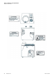
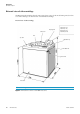
Description General description External view of ultracentrifuge The WX Series ultracentrifuge have the same external view, except for the model name printed on front cover. The following is the external view of the WX ultracentrifuge. External view of ultracentrifuge Display panel Safety cover 690 mm (27.2 in) 790 mm (31.1in) 850 mm (33.5 in) 1000 mm (39.4 in) Door Top deck Operation key Rotor rubber mat Power switch Front cover Note * This height is measured from level floor surface.
Description Design Design Control panel The control panel for the Sorvall WX Ultra series consists of a color screen, a touch sensitive display panel and a keyboard. The display panel incorporates an easy-to-read liquid crystal display. The display panel (field display) displays running conditions and running status (this screen is called the Run Screen), along with features such as Programmed Run, Rotors List, and User Customization Screens. Fig. 1-2 shows the display panel, and Fig.
Description Design Table 1-1 [Functions of the display panel-keyed by item no. to fig. 1-2] No. Name and Symbol Functions and actions (1) Field display Displays various fields. The SPEED, TIME, and TEMP fields give the current status indicator in the top row and the setting indicator in the bottom row. (For setting, see Section “Setting run conditions”.
Description Design Table 1-2 [Functions of keyboard-keyed by item no. to fig. 1-3] No. Name and Symbol Functions and actions (6) START key Starts rotor rotation. If VACUUM is off, this key activates the vacuum pump and starts temperature control. (7) STOP key Stops rotor rotation. (8) VACUUM key Starts up the vacuum pump and activates air vent (As soon as vacuum pump is on, temperature control starts.) Air vent for vacuum chamber after a run cannot be opened as long as the rotor is spinning.
Description Design Rotor chamber The structure of the rotor chamber (vacuum chamber) is shown in Fig. 1-4.
Description Design Safety devices (1) Containment Should a rotor failure occur, the guard ring will contain the contents of the rotor inside the centrifuge (Fig. 1-4). (2) Imbalance detector If during operation the vibration of the rotor becomes excessive due to serious imbalance or improper bucket setting, the imbalance detector detects the situation and decelerates the rotor immediately.
Description Design Rotor adapter Overspeed Decal The overspeed decal located on the rotor base has alternating black and white bands. The number of bands corresponds to the maximum permitted speed of the rotor. (See Fig. 1-5.) Overspeed decal Standard rotor with overspeed decal Figure 1-5 Standard rotor To protect the overspeed decal, be sure to store the rotor on the rotor stand provided. (See Fig. 1-6.
2 Operation The Sorvall WX Ultra series ultracentrifuges are capable of operation in more than one mode to meet a wide range of applications. The outline of each available mode is given below: Outline Reference Section Normal operation Speed Normal operation Time Speed Speed Programmed operation You can store set run conditions in memory for later use in repeated operation.
Operation Run preparation ω2T setting Section Setting w2T. Speed Calculates and displays the running time from the set values of speed and ω2T. Time Zonal operation is a mode of operation using a zonal rotor. Section Zonal operation. Optional features Speed Zonal operation Zonal speed Time Run preparation WARNING 1. Never use any materials capable of producing flammable or explosive vapors, or extreme exothermic reactions. 2.
Operation Run preparation Starting up the ultracentrifuge Before setting run conditions, display the run screen (screen for setting run conditions) (1) Displaying the Run Screen (screen for setting run conditions) 1. Turn on the POWER switch. 2. The initial screen appears. Initial screen 3. The Run Screen appears.
Operation Basic operation Preparing tubes/bottles and rotor Within 5 mm (0.197 in) Within 5 mm (0.197 in) The Sorvall WX Ultra series ultracentrifuges allow you to balance, by eye, tubes or bottles containing a sample solution and then centrifuge them. Make sure that the difference between meniscus levels of sample solution in tubes or bottles in within 5 mm (0.197 in) (See fig. 2-2).
Operation Basic operation [run screen] The screen for displaying run conditions and operational status is called the run screen. Speed, time, and temperature are displayed in two rows: the top row displays the current actual run conditions, while the bottom row displays the set run conditions. The acceleration (ACCEL) and the deceleration (DECEL) fields display set conditions.
Operation Basic operation Cursor key Cursor (blinking) The system does not accept a numerical input. The system accepts a numerical input. Use cursor keys to move to the next setting item. (2) Input wait state (1) Determined input state Figure 2-4 Setting indicator Note 1. If you enter the wrong value, press CE key to return to the input wait state. If you have pressed ENTER key, press a cursor key, enter the device into an input wait state, then enter the correct value. 2.
Operation Basic operation 1 Press cursor keys to enter the system into an input wait state. 2 Use cursor keys to move the cursor to the status indicator. (The arrows indicate the directions the cursor can be moved.. The system enters an input wait state. 2 hours 30 minutes The system enters an input wait state. Arrow The cursor in the setting item field blinks for about 30 seconds. Blinking means that the system enters an input wait state. 4 Use numeric keys to enter a setting.
Operation Basic operation The cursor blinks at one place. FUNCTION field For free coast, press HOLD/FREE. Display: F When one decimal place is not required, you do not need to enter . If you press , it becomes a “decimal place” input and the machine waits for an input of decimal places. Set it to 4.5 °C. Set it to 9 Set it to 7. • The FUNCTION field switches to the ID CODE field. • The number of units of ID CODE blinks. Can be set to any value in the range from 0 to 40 °C in increments of 0.1 °C.
Operation Basic operation Setting user ID code The USER ID CODE is a number to identify each user and can be set in up to 4 digits. When the user ID CODE is entered, the user record will be stored in the memory of the centrifuge and can be printed if a printout operation is done (optional). Entering a user ID CODE may not be always required for operation (Lockout feature optional).
Operation Basic operation Using Rotor Life Management The rotor type and serial number may be set in rotor management to allow for rotor logging within the centrifuge. Whether the rotor type and serial number for a particular rotor have been set or not, it does not affect the normal operation of the ultracentrifuge. However, you are advised to set the rotor type and serial number of the rotor for each run to allow effective rotor life management.
Operation Basic operating procedure Basic operating procedure There are two basic modes of operation, normal and zonal. The procedures for these two modes are shown in Fig. 2-5. START Zonal run Turn on the POWER. Open the chamber door and install the rotor. Normal run Close the door and set the run conditions. For information on how to set the run conditions, see Section Basic operation Reaches the set time, or press STOP. Rotor comes to a stop. Press VACUUM. Press VACUUM.
Operation Basic operating procedure Move the cursor to ZONAL in the Run Screen. Press 3, 0, ENTER Press START. Rotor accelerates to the set speed. Set run conditions. For information on how to set the run conditions, see Section Basic operation. Reaches the set time, or press STOP. Rotor decelerates to the zonal speed. The buzzer sounds. Press START. Press VACUUM and open the chamber door. Temperature control starts. The rotor rotates at the zonal speed. Load the sample, then cap the rotor.
Operation Basic operating procedure Normal operation Given below is a description of the operational procedure for a normal run. Speed Note Before starting up this machine, carefully read the operation manual for your rotor and make sure that you have selected the correct type of tubes and entered the correct amount of sample. Time Figure 2-6 Normal operation mode Step Operation and keystrokes Unit operation and considerations 1 Turn on the POWER switch on this machine.
Operation Basic operating procedure 7 The specified centrifugation time elapses (time-out). Or press STOP key. >> The rotor decelerates and stops. 8 The rotor brakes or coasts to a stop. >> Beeps to indicate that the rotor has stopped. 9 Press VACUUM key. >> The vacuum stops, the air leak valve gets activates, and the rotor chamber reaches atmospheric pressure. >> The door unlocks, and is able to be opened and closed. 10 Take out the rotor.
Operation Basic operating procedure Zonal operation Zonal operation is a mode of operation using a zonal rotor or continuous flow rotor for density gradient centrifugation with large amounts of sample or continuous sedimentation of particles from a large volume sample. The following zonal rotors are available for operation in the Sorvall WX Ultra series ultracentrifuges: TZ-28 sealed zonal rotor TCF-32 continuous flow zonal rotor The TZ-28 can only be operated in a sealed zonal mode.
Operation Basic operating procedure 2 On the Run Screen, move the cursor to ZONAL and enter the following by operating numeric keys to set the zonal operation mode. • Rotor begins to accelerate to the zonal speed. • Temperature control begins. 3 Set the run conditions. 4 Press the START key. >> For details, see Section Basic operation. Note The time being consumed at zonal speed is not counted as part of the run. 5 Install the seal assembly on the rotor. >> For details, see zonal rotor manual.
Operation Acceleration and deceleration rates 13 Open the chamber door. 14 Remove the cap assembly 15 Install the seal assembly and unload the sample. 16 On the Run Screen, move the cursor to ZONAL in the FUNCTION field and enter the following by operating numeric keys to set the normal operation mode. >> For details, see zonal rotor manual. >> Rotor decelerates to a stop.
Operation Acceleration and deceleration rates Code No. Acceleration time (minutes) from rest to 500 rpm Deceleration time (minutes) from 500 rpm to rest 9 Minimum time* Minimum time* 8 1 1 7 2 2 6 3 3 5 4 4 4 5 5 3 6 6 2 7 7 1 8 8 F - Coasting deceleration * Minimum time is the time for accelerating or decelerating by the driving motor with maximum torque. this time depends on the type of rotor in use.
Operation How to use the FUNCTION field Speed Allowable maximum speed 500 rpm 2 minutes 15 minutes 15 minutes 2 minutes Figure 2-9 Operation with setting ACCEL = 0 and DECEL = 0 How to use the FUNCTION field This ultracentrifuge incorporates a number of features. These features are displayed and specified in the FUNCTION field. The FUNCTION field is extended as shown in the following figure.
Operation How to use the FUNCTION field ID CODE: Sets an ID code. RLM: Switches the Run Screen to the rotor management field. PROG: Programs, stores, and recalls run conditions. This feature also offers a step-mode operation: a continuous run of multiple run conditions. RTC: Sets a start time or a finish time and runs the ultracentrifuge at a desired date and time. RCFmax: Maximum centrifugal force for the maximum radius rmax of the rotor used.
Operation How to use the FUNCTION field Programmed operation This ultracentrifuge has a programmed operation feature that stores run conditions. Storing run conditions which you often use allows you to recall those conditions as often as you wish, thus saving time in setting. (The saved run conditions will remain in effect even after the power switch is turned off.) This centrifuge incorporates the program areas indicated below. It has twenty memory areas and nine steps in each memory number.
Operation How to use the FUNCTION field Basic operation of the programmed operation feature Use cursor keys to select and ENTER key press ENTER key. Use cursor keys select to and ENTER key If you know which memory number stores the run condition. press ENTER key. Enter a memory number. To store, change or delete a program, or if you have forgotten the memory number where the run conditions are stored. ENTER key Press key to cause to blink and press ENTER key.
Operation How to use the FUNCTION field Note You cannot create, change, or delete a program while in running. Perform these operations while not in running. However, you can search the memory screen every time.
Operation How to use the FUNCTION field 1. Programming procedure for run conditions (creating or changing) Shown below is the procedure for storing (creating) or changing a run condition. Step Key operation 1 While in the Run Screen, use the cursor keys to move the cursor to PROG • RTC and press ENTER key. Then, move the cursor to PROG and press ENTER key. Screen display and considerations • The FUNCTION field switches to the PROGRAM field. • The MEMORY No. setting field blinks.
Operation How to use the FUNCTION field 5 6 Enter a desired condition. For example, select “SPEED”. Select a desired rotor. To select a desired rotor from the “Used Rotor List”: • The display switches to the Choose Rotor screen. • The display switches to the Used Rotor List screen. • You can search for the rotor number you need in the order starting with the latest date/time. To select a desired rotor from the “Rotor Catalog”: (1) Select “Rotor Catalog”.
Operation How to use the FUNCTION field 6 To select a desired rotor from the “Rotor Management”: (1') Select “Rotor Management”. • The display switches to the Rotor Management screen and the Rotor List is displayed. (2') Select a desired rotor using the upward or downward cursor key . (When using fixed angle rotor T-8100) (3') Select “Yes”. • The rotor type you have just entered appears in the top row in the screen. • The SPEED field in the SPEED priority screen blinks.
Operation How to use the FUNCTION field To change a run condition, use cursor keys to move to the item you want to change and then enter a value. 8 Press the downward cursor key to blink the value part of the message field in the bottom row. Then select “Yes”. • This diagram shows what you will get if you move the cursor and enter the TIME field into an input wait.
Operation How to use the FUNCTION field 10 Add Remark to the run conditions in the memory. (1) Press the ESC key. >> When you press ESC key, the bottom row message is displayed. (1) A selection field to input or delete Remark appears. (2) A selection field to select either inputting or deleting appears. (2) To add Remark to the run conditions in the memory, select “Yes”. (3) Select “Inputting Remark”. (3) The display switches to the Remark registration field. (4) Enter Remark in 8 characters or less.
Operation How to use the FUNCTION field 11 When the storing is over, press ESC key several times. >> The first push on ESC key switches the message display in the bottom row to what you see in process 3 as shown below. To run this centrifuge, select Running. >> Pushing ESC key a second time displays the Program Map screen shown in process 3. • Make sure that the condition is stored in memory number 3. >> The third push on ESC key switches you back to the Run Screen (program screen).
Operation How to use the FUNCTION field 2. How to perform a programmed operation Shown below is how to perform a “programmed operation”, that is, how to recall a stored set of run conditions and run this centrifuge accordingly. (a) If you know which memory unit number you need Step Key operation Screen display and considerations 1 Turn on the POWER switch on the centrifuge. >> The panel display appears. >> The door unlocks. 2 Install a rotor. >> Install the rotor securely on the shaft.
Operation How to use the FUNCTION field (b) If you do not know which memory number you need Step Key operation Screen display and considerations 1 Turn on the POWER switch of this machine. >> The panel display appears. >> The door unlocks. 2 Install a rotor. >> Install the rotor securely on the shaft. 3 While in the Run Screen, use cursor keys to move the cursor to PROG • RTC and then press ENTER key. Then, move the cursor to PROG and press ENTER key.
Operation How to use the FUNCTION field 7 To run the centrifuge, select “Yes”. >> If you select “Yes” • The display switches back to the Run Screen. Yes • The run conditions in memory appear in the respective fields. >> The message field in the bottom row displays PROG. >> If the STEP field displays what is shown in the figure below, that means that the memory number you have just called stores multiple run conditions (step-mode feature). For details, see Section Step-mode operation.
Operation How to use the FUNCTION field Step 1 Speed (rpm) Step 2 Step 3 Run time Figure 2-13 A typical step-mode run Thermo Scientific WX Ultra Series 2-33
Operation How to use the FUNCTION field Step Key operation 1 While in the Run Screen, use the cursor keys to move the cursor to PROG • RTC and press ENTER key. Then move the cursor to PROG and press ENTER key. Screen display and considerations • The FUNCTION field switches to the PROGRAM field. • The MEMORY No. setting field blinks. 2 Press the upward cursor key to cause PROGRAM to blink, then press ENTER key. • The display switches to the Program Map screen and the MEMORY No.
Operation How to use the FUNCTION field 4 Select “Creating or Changing.” • The message field in the bottom row switches to what you see on your left-hand side. 5 Enter a desired condition. To select SPEED, press • The display switches to the Choose Rotor screen. To select no rotor, press. • The display switches to the SPEED priority setting field and the SPEED area blinks. >> To select and enter RCFmax or RCFavg, see Section 1.
Operation How to use the FUNCTION field 8 Lastly, specify run conditions for step 3. • The entry of run conditions for step 3 is complete and step 4 is ready for input. Downward cursor key 9 Press the downward cursor key to blink the value part of the message field in the bottom row. Then select “Yes”. If you select “No”, the message field in the bottom row switches to what you see in process 4. Input a new setting.
Operation How to use the FUNCTION field 11 Add Remark to the run conditions in the memory. (1) Press the ESC key. >> When you press ESC key, the bottom row message is displayed. (1) A selection field to input or delete Remark appears. (2) To add Remark to the run conditions in the memory, select “Yes”. (2) A selection field to select either inputting or deleting appears. (3) Select “Inputting Remark”. (3) The display switches to the Remark registration field.
Operation How to use the FUNCTION field 14 To run the centrifuge, select Yes. >> If you select “Yes”: • The display switches back to the Yes Run Screen. • The run conditions of step 1 in memory appear in the respective fields. >> The message field in the bottom row displays PROG. 15 No >> If you select “No”, the message field in the bottom row displays what you see in process 10. Make the selection again.
Operation How to use the FUNCTION field (2) Deleting a program This section explains how to delete a set of run conditions stored in program memory. To delete a memory number, delete all steps in that memory number. Note While the instrument is running, you cannot delete a program memory number. Step Key operation 1 While in the Run Screen, use cursor keys to move the cursor to PROG • RTC and press ENTER key. Then move the cursor to PROG and press ENTER key.
Operation How to use the FUNCTION field 5 To delete this memory number, select Yes. Yes >> If you select “Yes”. • The system deletes all run conditions in memory number 3. (While in step mode, all steps get deleted.) No >> If you select “No”, the screen switches to what you see in process 3. Make the selection again. 6 Press ESC several times to move back to the Run Screen. >> If you delete a memory number, you can no longer run the centrifuge according to that number. (3) Other procedures 1.
Operation How to use the FUNCTION field 4. Control temperature: 4 °C 5. Acceleration mode: 9 6. Deceleration mode: 7 4h Speed (rpm) 100,000 START key ON 4:30 p.m, October 1 Automatic start at 5:30 a.m., October 2 Stop around 9:34 a.m. Finish time 9:30 a.m. Figure 2-14 A typical RTC run In this example, you set the above run conditions (2) through (6), set the finish time for RTC run to 9:30 a.m., October 1 and start the centrifuge.
Operation How to use the FUNCTION field 1. How to perform an RTC run Step Key operation 1 Screen display and considerations Set operational conditions while in the Run Screen. Use cursor keys to enter the SPEED part into an input wait, then press Move the cursor to PROG • RTC and press ENTER key. 2 3 Move the cursor to RTC and press ENTER key. Select the item you wish to set. To select the “Setting stop time”, press • The display switches to the RTC Setup screen.
Operation How to use the FUNCTION field 4 Use cursor keys and numeric keys to enter month, day, hours, and minutes. Then, press ENTER key. • Blink the PROG • RTC in the FUNCTION field. • To specify the run time (centrifugation time), do not set HOLD. Use ten keys to enter the run time instead. >> To set the hours, use a number between 0 and 23 (in the 24-hour system). >> Enter a time later than the current time.
Operation How to use the FUNCTION field Speed (rpm) 1. For an RTC run, the run mode indicator on the display panel displays the following: START key ON Time Automatic start Figure 2-15 Run mode display (RTC) 2. You cannot make an RTC setting in any of the following cases: a. When the Run Screen is set to HOLD (continuous run) Set the run time (centrifugation time) not to HOLD but to a numerical value. b. When it is past the start time Set the start time to a time later than the current time. c.
Operation How to use the FUNCTION field Making changes to the RTC settings This section shows how to cancel or make changes to the RTC settings you have made. If you have already started an RTC run, press STOP to abort the RTC first. Press STOP to cancel the RTC run. Step Key operation 1 (1) While in the Run Screen, use cursor keys to move the cursor to PROG • RTC and then press ENTER key. Screen display and considerations (2) Use cursor keys to move the cursor to RTC and then press ENTER key.
Operation How to use the FUNCTION field 3 Making a change to date and time settings (1) Select “Setting stop time” or “Setting start time”. To change the “Setting stop time”, press (2) Perform process 4 and later ones in 1. How to perform an RTC run mentioned above and change the date and time settings. • The screen switches to a screen where you can enter a stop time (or start time). See Section 1. How to perform an RTC run.
Operation How to use the FUNCTION field 2 Press cursor keys to blink RTC and then press ENTER key. 3 [Before starting the RTC run] (1) Select “Deleting the set RTC”. • The message indicator in the bottom row changes. >>If you select “Yes” (2) Select “Yes”. • The RTC setting has been canceled. >> If you select “No”, you will get the display you see in process 2. Make a selection again. [After starting the RTC run] (1') Select “Deleting the set RTC”. • The message indicator in the bottom row changes.
Operation How to use the FUNCTION field ii) Select “Cancel RTC-Start run”. iii) Select “Continue RTC”. • The display switches back to the Run Screen. (3) Press ESC after process (2') i) or ii). >> The RTC in the message indicator in the bottom row disappears. Displaying and setting RCF This ultracentrifuge stores the maximum and average radii of each rotor in internal memory.
Operation How to use the FUNCTION field Step Key operation Screen display and considerations 1 While in the Run Screen, set a speed. >> See Section Setting run conditions. 2 Use cursor keys to move the cursor to RCF • ω2T and press ENTER key. • The FUNCTION field switches to what is shown in the diagram to the left, and the RCFmax field blinks. 3 Move the cursor to RCFmax (or RCFavg) and press ENTER key. • The RCF display field displays the RCF value of the rotor.
Operation How to use the FUNCTION field • When the rotor to be used is not identified (when rotor type is displayed in the message display field) Step Key operation Screen display and considerations 1 Set the speed on the Run Screen. >> See Section Setting run conditions. 2 (1) Use cursor keys to move the cursor to RCF • ω2T and press the ENTER key. • The contents of the display in the FUNCTION field change. • The RCFmax area blinks.
Operation How to use the FUNCTION field 4 Select a desired rotor. To select a desired rotor from the “Used Rotor List”: • The display switches to the Used Rotor List screen. • You can search for the rotor number you need in the order starting with the latest date/time. To select a desired rotor from the “Rotor Catalog”: (1) Select “Rotor Catalog”. • The display switches to the Rotor List screen. (2) Select Fixed Angle Rotors in the rotor types.
Operation How to use the FUNCTION field 4 To select a desired rotor from the “Rotor Management”: (1') Select “Rotor Management”. • The display switches to the Rotor Management screen and the Rotor List is displayed. (2') Select a desired rotor using the upward or downward cursor key . (When using fixed angle rotor T-8100) (3’) Select “Yes”. • The display switches back to the Run Screen and the selected rotor type is displayed in the message display field of the bottom row.
Operation How to use the FUNCTION field How to set an RCF value Enter a rotor number and an RCF value, and the machine will calculate, set, and display the speed. Shown below is the procedure. Step Key operation Screen display and considerations 1 While in the Run Screen, set a speed. >> See Section Setting run conditions. 2 (1) While in the Run Screen, use cursor keys to move the cursor to RCF • ω2T and press ENTER key. (2) Move the cursor to RCFmax (or RCFavg) and press ENTER key.
Operation How to use the FUNCTION field 4 Select a desired rotor. To select a desired rotor from the “Used Rotor List”: (1) Enter No. that is found in the Rotor List. • The display switches to the Used Rotor List screen. To select a desired rotor from the “Rotor Catalog”: (1)' Select “Rotor Catalog”. • The display switches to the Rotor • You can search for the rotor number you need in the order starting with the latest date/time. List screen. (2)' Select Fixed Angle Rotors in the rotor types.
Operation How to use the FUNCTION field 4 To select a desired rotor from the “Rotor Management”: (1) Select “Rotor Management”. • The display switches to the Rotor Management screen and the Rotor List is displayed. (2) Select a desired rotor using the upward or downward cursor key . (When using fixed angle rotor T-8100) (3) Select “Yes”. • The display switches back to the Run Screen and the selected rotor type is displayed in the message display field of the bottom row.
Operation How to use the FUNCTION field Note 1. Press ESC key to cancel the RCF field. 2. When you run this centrifuge at a speed determined based on an RCF value, a slight rounding may occur (of up to 2%) between the set RCF value and the actual value, because the speed setting is set in increments of 100 rpm. Setting ω2T This machine is provided with a function to perform an ω2T run. To perform an ω2T run, set the ω2T value instead of the run time.
Operation How to use the FUNCTION field Step Key operation Screen display and considerations 1 Set the Speed in the Run Screen. >> See Section Setting run conditions. 2 (1) Use cursor keys to move the cursor to RCF • w2T on the Run Screen and press the ENTER key. • The contents of the display in the FUNCTION field change. • ω2T blinks. (2) Use cursor keys to move the cursor to w2T and press the ENTER key. • The FUNCTION field switches to the ω2T field.
Operation How to use the FUNCTION field Note When the ω2T display field reaches the set value of ω2T, the machine decelerates and stops. During deceleration, the ω2T display field continues to accumulate value until the rotor stops and the run ends. Defrost function If the chamber door is left open between low temperature runs, moisture from the ambient air humidity can condense (and even freeze) on the cold evaporator chamber walls.
Operation How to use the FUNCTION field Note 1. Before starting defrost operations, wipe away any moisture and close the door. 2. The temperature rise of the rotor due to defrost operations (for 10 minutes) should be 1 C or less. 3. During rotor acceleration or at set speed, defrost can be set but the defrost function is not available. 4. If DEF is selected during accel or set speed, it will not function until the run times out or stop is pressed.
Operation Rotor management 2. Resetting zonal operation Step Key operation Screen display and considerations 1 On the Run Screen, use cursor keys to move the cursor to ZONAL in the FUNCTION field, and press or • ZONAL in the message field disappears and the machine status switches to normal operation. Note If no key operation is performed for 30 seconds, the cursor disappears and any entry is disabled. At that time, press the cursor key to cause the cursor to blink once again.
Operation Rotor management To utilize this feature, each time a rotor is used it must be recorded by the ultracentrifuge. To do this, a rotor must be initially registered in the Rotor Management software. Each time the rotor is used in the Sorvall WX Ultra series ultracentrifuge, it must be selected from the Rotor Management Screen prior to starting the run. Additionally, should the rotor be used in other ultracentrifuges, the Rotor Management information can be edited to record this usage.
Operation Rotor management Step Key operation Screen display and considerations 1 While in the Run Screen, use the cursor keys to move the cursor to RLM and press ENTER key. Switch each page of the Rotor List by using the left and right arrow keys ( 2 and ). Use the cursor keys ( • The display switches to the Rotor Management screen and the Rotor List is displayed. and ) to move the cursor to the line that is not yet registered (New Rotor), and press the ENTER key.
Operation Rotor management 5 Select “T-890” rotor. • Specifications of the T-890 rotor are displayed. 6 After checking the specifications of the rotor, enter “Yes”. • The display switches to the Rotor Management screen. • You can enter a serial number of the rotor. 7 As the cursor has been moved to the S/N field, enter serial No. of the rotor by using numeric keys. (Do not press the ENTER key.) • The cursor moves to the Runs field. You can enter the total number of runs.
Operation Rotor management Thus the rotor has been registered. Note When the ENTER key is pressed in the above steps “7” to “9”, “0” is registered as a numeric value in each step. When the serial number must be corrected, the rotor must be deleted once and the value must be reentered from step “1”. (See the next page.) In the steps “7” to “9”, it is possible to change the value repeatedly by moving the cursor with the arrow keys unless the ENTER key is pressed.
Operation Rotor management Updating the existing data for a rotor When a rotor is registered in the Sorvall WX Ultra series ultracentrifuges without a Rotor Management function, both Total number of runs and Total number of hours can be updated. The updated value is accepted only when it is greater than the registered value. It must not be smaller than the registered value.
Operation When power failure occurs Thus, the current total number of runs and hours have been updated. When power failure occurs DANGER Before removing the cover, top deck, or other components. for maintenance, be sure to turn off the POWER switch of the centrifuge. Then unplug the power cord from the wall outlet, and wait at least three minutes to avoid the risk of electrical shock. WARNING 1. Never open the door during rotation. 2. Never touch the rotor during rotation.
Operation When power failure occurs Table Cabinet cover Front cover M5 hexagon head bolt for fixing the front cover (4 pcs.) Figure 2-16 Removing the front cover (4) Open the air vent (by turning the vacuum release screw on the left of the vacuum chamber counterclockwise) to let air into the rotor chamber. When the pressure in the rotor chamber reaches atmospheric pressure, do not forget to tighten the vacuum release screw as it was before. (See Fig. 2-16.
Operation When power failure occurs Handle Vacuum release screw Power breaker Vacuum chamber Door unlock wire Figure 2-17 Ultracentrifuge with the front cover removed M5 hexagon head bolt for fixing the front cover (4 pcs.) Figure 2-18 Installing the front cover (7) Turn on the power breaker. WARNING off.
Operation Features of the menu screen Features of the menu screen Press MENU key on the key board, and the Menu Screen will appear. This feature is designed to allow you to use the Sorvall WX Ultra series with additional options including: (1) Centrifuge scheduler (2) User list (3) Alarm information (4) Rotor catalog (5) User customization routines Key in the number of the item you wish to use and press the ENTER key, and the respective screen will appear.
Operation Features of the menu screen 3 Enter an ID Code that is already registered. (4-digit number) • The User Name corresponding to the ID Code is displayed. (In this example, ABC lab. is displayed.) ID code 4 Select “Reserve”. • The current date/time is displayed at the reservation time of the specified reservation No.3. 5 Use cursor keys to move the cursor to the position at which you want to change the date/time of reservation, and enter a number by using numeric keys.
Operation Features of the menu screen 2 3 Use cursor keys to move the cursor to reservation No. you want to delete. (In this example, No. 3 is selected.) Enter the ID Code of the reserving person proper. (4-digit number) ID code 4 • The ID Code input field is displayed in the message field in the bottom row. • When the ID Code is accepted, the reserve/delete selection message is displayed in the message field of the bottom row. Select “Delete”.
Operation Features of the menu screen • ID code and user name ID Code Password comprised of a 4-digit number. This number is not displayed when the centrifuge is operated. The mark * is displayed instead of the number. User Name Character string of 8 digits or less. The user name corresponding to the ID Code is displayed on the screen. Alphabetical upper-case and lower-case characters and several types of special characters are available.
Operation Features of the menu screen 3 Select “Creating”. • The User List screen switches to the User Name screen. 4 5 Use cursor keys to highlight a character and press the ENTER key to select it. • Screen for entry of characters After completion of the entry of characters, use cursor keys to move the cursor to SET and press the ENTER key to register the character string. • The cursor is positioned at SET. • The confirmation message is displayed. 6 Select “Yes”.
Operation Features of the menu screen 2. Change of User Name Note Changing a User Name is limited to the person (with the same ID Code) who registered it and wants to change it. Step Key operation 1 On the Menu Screen, select “User List”. Screen display and considerations • The Menu Screen switches to the User List screen. • For a change, select a registered No. 2 3 Use cursor keys to move the cursor and press the ENTER key. (Select No.9.
Operation Features of the menu screen 6 After entering characters, use cursor keys to move the cursor to SET and press the ENTER key to register the character string. • The cursor is positioned at SET. • The confirmation message is displayed. 7 Select “Yes”. • The changed User Name is displayed together with its date of registration on the User List screen. 3. Deleting a user name setting Note Deleting a User Name is limited to the person (with the same ID Code) who registered it.
Operation Features of the menu screen 4 5 Enter the ID Code used for registering No.9 by using numeric keys. • The confirmation message is displayed. Select “Yes”. • The User Name and ID Code of No.9 disappear. >> When you select “No.” the display switches back to the screen display of Step 2. 6 Press the ESC key. >> The User List screen switches to the Menu Screen. Alarm information The Alarm Information screen displays the contents of the alarm signals and what to do when such signals occur.
Operation Features of the menu screen Rotor catalog You can refer to rotor types and rotor specifications that are available. Step Key operation 1 On the Menu Screen, select “Rotor Catalog”. 2 3 Screen display and considerations • The display switches to the Rotor List screen. To refer to the fixed angle rotor P100AT2, select “Fixed Angle Rotors” on the Rotor List screen. • The display switches to the Fixed Angle Rotor List screen. Select the “T-8100” rotor.
Operation Features of the menu screen Figure 2-21 User Customizations screen Figure 2-22 Screen Utilities screen 2. Screen Utilities settings 1. Display language and select Japanese or English. Key in the number of the desired language and press ENTER key. 2. Changing from the Run Screen >> Normal: Displays the Run Screen. >> Graphics and zoom: Twenty seconds after the actual speed reaches the set speed while in the Run Screen, the display will automatically switch to the screen shown in Fig.
Operation Features of the menu screen Figure 2-24 Zoom screen 3. Changing date and time Use this option to precisely set the current time setting of the internal clock. Set an exact date and time for RTC operation. Use cursor keys and numeric keys and then press ENTER to make a setting. 4. Screen contrast Use cursor keys and to adjust the contrast. Low contrast High contrast Figure 2-25 Contrast adjustment Note >> To get back to the Run Screen, press ESC several times.
Operation Features of the menu screen (2) Run Time range This function selects one of the following two items as the running time setting range in the normal operation mode or zonal operation mode: >> Accel + Run Time from pressing the START key to a start of deceleration: T1 (ordinary running time). Speed T1 T2 [Normal operation] Time Speed T1 T2 [Zonal operation] Time Figure 2-27 Run time range setting Note The vacuum waiting time is not counted in the normal operation.
Operation Print utilities (option) (4) Zonal speed This function can change (in units of 100 rpm) the zonal speed in the range of 2,000 to 3,000 rpm. For the zonal speed, see Section Zonal operation) Figure 2-29 Run condition setting screen 4. Select option unit This function allows you to set one of the following optional units through the RS232C.
Operation Print utilities (option) Figure 2-31 PRINT UTILITIES Screen Note • Select “1. Printer” of “4. Select Option Unit” in the User Customization Routines screen. Refer to Section User Customizations. Operating procedure No. Item Operating procedure 1 Machine Log (1) Select the corresponding item number on the Print Utilities Menu screen. 2 Rotor Management 3 Rotor Log (1) On the Print Utilities Menu screen, select “3. Rotor Log”. • The display switches to the Rotor Management screen.
Operation Print utilities (option) 7 Print program (1) On the Print Utilities menu screen, select “7. Print Program”. • The display switches to the Program Map screen. (2) Select a program No. to be printed. 8 User log (1) On the Print Utilities Menu screen, select “8. User Log”. • The display switches to the User List screen. (2) Move the cursor to select a User Name and perform printing. 9 Machine Management (1) On the Print Utilities menu screen, select “9. Machine Management”.
Operation Print utilities (option) Contents of print utilities No. Item 1 CENTRIFUGE RUN RECORDS >> Ultracentrifuge run records for a maximum of 40 runs can be printed out at a time. >> Once the ultracentrifuge run records are printed out, they are gone. Therefore, if necessary, save the produced printout for future reference. 2 RUN RECORDS OF ALL ROTORS >> Run records of all the rotors registered are printed out.
Operation Print utilities (option) 3 RUN RECORDS OF A ROTOR >> Run records of a particular rotor are printed out; a maximum of 20 runs can be printed out at a time. >> When you select this option, a list of registered rotors is displayed. Move the cursor to the rotor the run records of which you want to print out, and then press the ENTER key. >> Once the run records of the run are printed out, they are gone. Therefore, if necessary, save the produced printout for future reference.
Operation Print utilities (option) 7 LISTING OF ALL EXISTING PROGRAMS >> A list of all the programs in the ultracentrifuge is printed out. 8 USER LOG OUTPUT >> The centrifuge user's run log is printed out up to 20 runs. >> Once the user log is output, the previous run record is deleted and cannot be printed out once again. 9 MACHINE MANAGEMENT OUTPUT >> The running time and the total number of revolutions are totaled for each user.
Operation Print utilities (option) 1) Automatic printing of run records Ultracentrifuge run records are retained in the run record buffer. This buffer can hold a maximum of 40 records at any given time. When the buffer becomes full, all of the 40 records are automatically printed out, except when the PRINTOUT AFTER EACH RUN options is toggled on. In this case, the result of the last run made is printed out, followed by all the run records in the buffer.
Operation Lockout (optional) Lockout (optional) Note When installing the Lockout Procedure for the first time, all memory is cleared. If obtaining Lockout Option after centrifuge has been installed, it will be necessary for service to record and then re-enter pertinent memory information such as total revolutions, total running count, and total running time. In the function field, all rotor life management (RLM) and program (PROG) information must also be recorded and re-entered.
3 Maintenance Before conducting any maintenance, always read the following: DANGER Before removing the cover, top deck, or other components. for maintenance, be sure to turn off the POWER switch of the centrifuge. Then unplug the power cord from the wall outlet, and wait at least three minutes to avoid the risk of electrical shock. WARNING 1. Be sure to take necessary safety measures before using materials which are toxic, radioactive, or contaminated with pathogenic micro-organisms. 2.
Maintenance Cabinet Drive spindle Wipe the drive spindle with a soft dry cloth every run to reduce the chance of the rotor sticking to the spindle. Temperature sensor Door seal o-ring Drive spindle Figure 3-1 Rotor chamber Cabinet Use a mild, non-alkaline detergent and water to wipe the top deck and cabinet panels clean. Replacement parts To order replacement parts, contact your local authorized Thermo representative.
Maintenance Service decontamination policy instruction manual contains specific guidance about cleaning and decontamination methods appropriate for the product it describes. Clean and decontaminate your centrifuge as follows: a. Remove rotor from the rotor chamber. b. Decontaminate door and rotor chamber using an appropriate method. 2. Complete and attach Decontamination Information Certificate (in the back of your rotor or instrument manual) to the centrifuge before servicing or return to Thermo facility.
4 Troubleshooting Before troubleshooting, always read the following: DANGER Before removing the top deck, or other components for troubleshooting, always turn off the POWER switch of the centrifuge. Then unplug the power cord from the wall outlet, and wait at least three minutes to avoid the risk of electrical shock. WARNING 1. Be sure to take necessary safety measures before using materials which are toxic, radioactive, or contaminated with pathogenic micro-organisms. 2.
Troubleshooting 1. Searching for Alarm Information No. Key operation 1 A “DOOR” alarm signal occurs. Screen display and considerations • An alarm message appears in the message field of the Run screen. 2 Press MENU key. • The display switches to the Menu screen. 3 Select “ALARM INFORMATION”. • The “ALARM INFORMATION” screen appears. >> The screen related to the current alarm signal is displayed before any other screen. >> To get back to the Run Screen, press ESC key twice. 2.
Troubleshooting Diagnosed problems - requiring maintenance ROTOR 1. The rotor is not seated on spindle. • Install rotor. IMBALANCE 1. Rotor is not properly balanced, and abnormal vibration has occurred in the rotor. 2. Rotor cover or cap is not properly tightened. • Check if the sample tubes exceed allowable imbalance level. • Check if any one of the tubes is deformed, and if there is any sign of sample leakage. • Tighten rotor cover or cap securely. SPEED 1.
5 Preinstallation CAUTION An authorized Thermo Field Service Engineer must perform installation and electrical modifications of the centrifuge or the centrifuge warranty will be void. The information on these two pages describes the location requirements and the electrical services that you must make provision for prior to installation of the centrifuge by an authorized Thermo Field Service Engineer. The requirements may be modified, if necessary, to comply with state or local ordinances.
Preinstallation Electrical requirements Electrical requirements The centrifuge must be connected to the power source that is specified on the nameplate on the left side of the instrument panel. The centrifuge can be wired for split two-phase or split three-phase application and international color coding of wires used, as appropriate. If required, wiring will be done when the centrifuge is installed.
Preinstallation Moving the ultracentrifuge 4. When the instrument is level, check that the four leveling screws are secured to the floor. Level Drive shaft Figure 5-3 Level placement Moving the ultracentrifuge CAUTION Before moving the ultracentrifuge, be sure to remove the rotor from the drive shaft and store it in a safe place. When moving the ultracentrifuge, disconnect the power cord and unscrew the leveling screws with a wrench to lower the caster to the floor.
6 Specifications Model Sorvall WX Ultra Series Sorvall WX 100 Ultra Sorvall WX 90 Ultra Sorvall WX 80 Ultra Maximum speed 100,000rpm 90,000rpm 80,000rpm Maximum RCF 802,006 x g (T-8100) 692,149 x g (T-890) 602,644 x g (T-880) Speed control accuracy ±10 rpm (1,000 rpm to maximum speed) Acceleration/deceleration control About 5 minutes from 0 to 100,000 rpm or vice versa (P100AT2) Rotor temperature control/display accuracy ±0.
Specifications • EN 61000-3-3 (*) EMC: Electromagnetic compatibility The Sorvall WX Ultra series centrifuges satisfy CE marking requirements. The CE marking is an international symbol, which shows that the product conforms to EC directives.
7 Supply list The items listed below are those supplied with the ultracentrifuge. Thermo Scientific Item name Part no. Q’ty Instruction manual 45912 1 Vacuum grease 65937 1 Vacuum pump oil 45128 1 M5 screw 3 Hex.
Supply list Optional items Item name Part no.
A Service Decontamination Policy WARNING Because of the characteristics of the samples likely to be processed, biological or radioactive contamination may occur. Always be aware of this possibility and take normal precautions. Use appropriate decontamination procedures should exposure occur.
Service Decontamination Policy be borne by the sender. Decontamination Information Certificates are included with these instructions. Additional certificates are available from the local Account Representative or Field Service Engineer. In the event these certificates are not available, a written statement certifying that the unit has been properly decontaminated and outlining the procedures used will be acceptable.
B Condensed operating instructions Sorvall® WX Ultra series ultracentrifuge These instructions are intended to be used only as a guide to operate the Sorvall WX Ultra series ultracentrifuge. We recommend that you read the Instruction Manual thoroughly, particularly all WARNINGS and CAUTIONS, before operating the ultracentrifuge. Before the run Turn the ultracentrifuge power ON. Open the chamber door and wipe the chamber dry. Place the rotor carefully on the drive spindle.
C GLASS NEOPRENE NORYL® NYLON PET1, POLYCLEAR®,CLEARCRIMP®CCCLEARCRIMP® POLYALLOMER POLYCARBONATE POLYESTER, GLASS THERMOSET POLYTHERMIDE POLYRTHYLENE POLYPROPYLENE POLYSULFONE M S - S U S S U S S - S S S S Acetaldehyde S - U U - - - M - U - - - M U U U Acetone M S U U S U M S S U U S U S U U Acetonitrile S S U - S M S - S S U S U M U Alconox U U S - S S S - S S S S S Allyl Alcohol - - - U - - S - - - - S Alum
BUNA N CELLULOSE ACETATE BUTYRATE POLYURETHANE ROTOR PAINT COMPOSITE Carbon Fiber/Epoxy DELRIN® ETHYLENE PROPYLENE GLASS NEOPRENE NORYL® NYLON PET1, POLYCLEAR®,CLEARCRIMP®CCCLEARCRIMP® POLYALLOMER POLYCARBONATE POLYESTER, GLASS THERMOSET POLYTHERMIDE POLYRTHYLENE POLYPROPYLENE POLYSULFONE POLYVINYL CHLORIDE RULON A®, TEFLON® SILICONE RUBBER STAINLESS STEEL TITANIUM TYGON® VITON® Cesium Bromide M S S - S S S - S S S S S S S - - S S S S S S M S S S Cesium Chl
Formaldehyde (40%) M M M S S S S M S S S S M S Glutaraldehyde S S S S - - S - S S S S S Glycerol M S S - S S S S S S S S Guanidine Hydrochloride U U S - S S S - S S S ® S S S - - - S - S S Hexane S S S - S S S - S Isobutyl Alcohol - - M U - - S S Isopropyl Alcohol M M M U S S S Iodoacetic Acid S S M - S S Potassium Bromide U S S - S Potassium Carbonate M U S S Potassium Chloride U S S Potassium Hydroxide (5
S - S U - - S - - S M - N-Butyl Phthalate S S U - S S S - S U U N, N-Dimethylformamide S S S U S M S - S S Sodium Borate M S S S S S S S S Sodium Bromide U S S - S S S - Sodium Carbonate (2%) M U S S S S S Sodium Dodecyl Sulfate S S S - S S Sodium Hypochlorite (5%) U U M S Sodium Iodide M S S Sodium Nitrate S S Sodium Sulfate U Sodium Sulfide S S S S M S M S S - S U S M S S S S M M S M - S - S S U U U M -
BUNA N CELLULOSE ACETATE BUTYRATE POLYURETHANE ROTOR PAINT COMPOSITE Carbon Fiber/Epoxy DELRIN® ETHYLENE PROPYLENE GLASS NEOPRENE NORYL® NYLON PET1, POLYCLEAR®,CLEARCRIMP®CCCLEARCRIMP® POLYALLOMER POLYCARBONATE POLYESTER, GLASS THERMOSET POLYTHERMIDE POLYRTHYLENE POLYPROPYLENE POLYSULFONE POLYVINYL CHLORIDE RULON A®, TEFLON® SILICONE RUBBER STAINLESS STEEL TITANIUM TYGON® VITON® S - S S S - S S S S S S U S S S S S S S S M S S S Sulfosalicylic Acid U U S S
C Chemical Compatibility Chart Key S Satisfactory M M = Moderate attack, may be satisfactory for use in centrifuge depending on length of exposure, speed involved, etc.; suggest testing under actual conditions of use. U U = Unsatisfactory, not recommended. -- Performance unknown; suggest testing, using sample to avoid loss of valuable material. Chemical resistance data is included only as a guide to product use.
D WARRANTY THERMO FISHER SCIENTIFIC MAKES NO WARRANTY OF ANY KIND, EXPRESSED OR IMPLIED, INCLUDING THAT OF MERCHANTABILITY OR FITNESS FOR A PARTICULAR PURPOSE EXCEPT AS STATED IN THIS WARRANTY POLICY STATEMENT.
D WARRANTY c. The drive unit shall not be modified, disassembled, or repaired by any party but Thermo Fisher Scientific or by a service representative authorized, in writing, by Thermo Fisher Scientific. If any defect should happen to the drive unit within the afore said warranty period, the defective drive unit shall be replaced at no cost to the Buyer. Extended Warranties are conditional on the instrument being correctly maintained by authorized Service Representatives on an annual basis.
E Contact Information United States 866-9-THERMO +1 866 984 3766 Canada +1 866 984 3766 Austria +43 1 801 400 Belgium +32 2 482 30 30 Germany 08001 536 376 +49 6184 90 6940 Thermo Scientific France +33 2 2803 2180 Italy +39 02 02 95059 434-254-375 Netherlands +31 76 571 4440 Nordic / Baltic Countries +35 89 329 100 Russia/CIS +7 (812) 703 42 15 E-1
E Contact Information Spain +34 932 23 09 18 Portugal +34 932 23 09 18 Switzerland +41 44 454 12 12 UK / Ireland +44 870 609 9203 China +86 21 6865 4588 +86 10 8419 3588 India 1800 22 8374 +91 22 6716 2200 Japan +81 45 453 9220 Other Asian Countries +852 2885 4613 Other Countries +49 6184 90 6940 +33 2 2803 2180 E-2 Thermo Scientific